This discussion has been locked.
You can no longer post new replies to this discussion. If you have a question you can start a new discussion

GPIO/GPIOTE interrupts not triggered at every event

Hi,

My goal is to generate a GPIO or GPIOTE interrupt and inside the ISR sample 8-bits from GPIO.

I tried modifying two sample projects to achieve this, the NRFX and the button projects, but I got similar results from both. I started by toggling a pin inside the ISR to check if the ISR is triggered for every event and I found that it is not happening for higher frequencies.

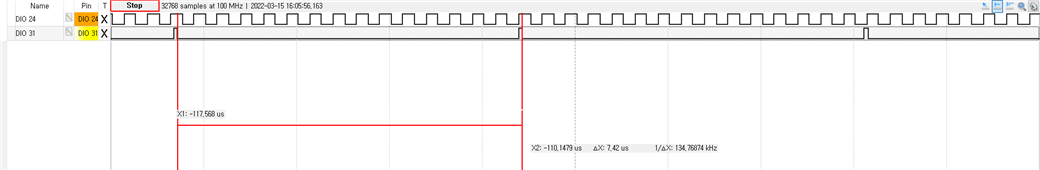
See some examples below of various input frequencies to the GPIOTE pin and toggling another pin in the GPIOTE_ISR.

2 MHz input signal

500 kHz input signal

100 kHz input signal

50 kHz input signal

10 kHz input signal

Is this an expected result? Can it be improved?

Thank you.

Parents
  • Hi,

    With high frequencies you will not have time for many instructions in the ISR before you run out of time. So without having seen your code I expect that is the problem. What is the end goal here? Doing things in SW this rapidly does not generally seem like a good idea (and if you are able to do wat you want here, you would not be able to do much else if anything as the CPU is more or less always busy handling the GPIOTE interrupts.

    Regarding using a different pin you can for instance make an overlay where you map the sw0 alias to something else, and that should work out of the box. How have you selected another pin?

  • Hi.

    With high frequencies you will not have time for many instructions in the ISR before you run out of time. So without having seen your code I expect that is the problem. What is the end goal here? Doing things in SW this rapidly does not generally seem like a good idea (and if you are able to do wat you want here, you would not be able to do much else if anything as the CPU is more or less always busy handling the GPIOTE interrupts.

    So, what is seen in the pictures above is expected and can not be improved by adjusting the configurations?

    This is how I changed the pin:

    &button0 {
        gpios = <&gpio1 15 (GPIO_PULL_UP | GPIO_ACTIVE_LOW)>;
    };
    I noticed that if I use the preassigned pin (p0.23) the interrupt is triggered, but if I change the pin as above and connect the signal to p1.15 the GPIOTE ISR is not called.
Reply
  • Hi.

    With high frequencies you will not have time for many instructions in the ISR before you run out of time. So without having seen your code I expect that is the problem. What is the end goal here? Doing things in SW this rapidly does not generally seem like a good idea (and if you are able to do wat you want here, you would not be able to do much else if anything as the CPU is more or less always busy handling the GPIOTE interrupts.

    So, what is seen in the pictures above is expected and can not be improved by adjusting the configurations?

    This is how I changed the pin:

    &button0 {
        gpios = <&gpio1 15 (GPIO_PULL_UP | GPIO_ACTIVE_LOW)>;
    };
    I noticed that if I use the preassigned pin (p0.23) the interrupt is triggered, but if I change the pin as above and connect the signal to p1.15 the GPIOTE ISR is not called.
Children
  • I tried to change the INPUT_PIN via the .overlay file using other pins from the P0 port and the interrupt was triggered, but I couldn't trigger interrupts using any pin from the P1 port. Is there something I need to change in the project to be able to use pins from port P1 as input?

  • Ah, I did not notice this before, but the nrfx sample does not handle GPIO pins from port 1. When yo use a pin from port 1, the pin number should be 32 + the P1 pin. So for instance, P1.15 is pin 47. This is normally handled more elegantly when using the Zephyr GPIO API, but when using nrfx directly that is not the case. You can for instance to it like this, though:

    Specify the pin in an overlay file like you have before:

    &button0 {
    	gpios = <&gpio1 15 (GPIO_PULL_UP | GPIO_ACTIVE_LOW)>;
    };

    Then you can check the port and add 32 as needed as shown in this diff from the nrfx sample in nRF Connect SDK 1.9.1:

    diff --git a/samples/boards/nrf/nrfx/src/main.c b/samples/boards/nrf/nrfx/src/main.c
    index 5c2f2a6b55..64e60d6534 100644
    --- a/samples/boards/nrf/nrfx/src/main.c
    +++ b/samples/boards/nrf/nrfx/src/main.c
    @@ -17,9 +17,10 @@
     #include <logging/log.h>
     LOG_MODULE_REGISTER(nrfx_sample, LOG_LEVEL_INF);
     
    -#define INPUT_PIN	DT_GPIO_PIN(DT_ALIAS(sw0), gpios)
     #define OUTPUT_PIN	DT_GPIO_PIN(DT_ALIAS(led0), gpios)
     
    +uint32_t m_input_pin;
    +
     static void button_handler(nrfx_gpiote_pin_t pin, nrf_gpiote_polarity_t action)
     {
     	LOG_INF("GPIO input event callback");
    @@ -27,7 +28,15 @@ static void button_handler(nrfx_gpiote_pin_t pin, nrf_gpiote_polarity_t action)
     
     void main(void)
     {
    -	LOG_INF("nrfx_gpiote sample on %s", CONFIG_BOARD);
    +	if (strcmp(DT_GPIO_LABEL(DT_ALIAS(sw0), gpios), "GPIO_1") == 0) {
    +		m_input_pin = 32 + DT_GPIO_PIN(DT_ALIAS(sw0), gpios);
    +	}
    +	else {
    +		m_input_pin = DT_GPIO_PIN(DT_ALIAS(sw0), gpios);
    +	}
    +
    +	LOG_INF("nrfx_gpiote sample on %s. Input pin is: %u", CONFIG_BOARD, m_input_pin);
    +
     
     	nrfx_err_t err;
     
    @@ -56,7 +65,7 @@ void main(void)
     	/* Initialize input pin to generate event on high to low transition
     	 * (falling edge) and call button_handler()
     	 */
    -	err = nrfx_gpiote_in_init(INPUT_PIN, &in_config, button_handler);
    +	err = nrfx_gpiote_in_init(m_input_pin, &in_config, button_handler);
     	if (err != NRFX_SUCCESS) {
     		LOG_ERR("nrfx_gpiote_in_init error: %08x", err);
     		return;
    @@ -77,7 +86,7 @@ void main(void)
     		return;
     	}
     
    -	nrfx_gpiote_in_event_enable(INPUT_PIN, true);
    +	nrfx_gpiote_in_event_enable(m_input_pin, true);
     	nrfx_gpiote_out_task_enable(OUTPUT_PIN);
     
     	LOG_INF("nrfx_gpiote initialized");
    @@ -100,7 +109,7 @@ void main(void)
     	 * the button is pressed, the LED pin will be toggled.
     	 */
     	nrfx_gppi_channel_endpoints_setup(channel,
    -		nrfx_gpiote_in_event_addr_get(INPUT_PIN),
    +		nrfx_gpiote_in_event_addr_get(m_input_pin),
     		nrfx_gpiote_out_task_addr_get(OUTPUT_PIN));
     
     	/* Enable (D)PPI channel. */
    

    (I have kept the output pin as is here, but you can change that as well). 

  • Thank you. That solved the pin problem. But if I may, I still have a question that is related to the initial topic of this post.

    Q - If we are doing operations that are unrelated to the peripherals, these operations are controlled by the main clock (128 / 64 MHz in the case of the nRF5340), but what clock controls the process of entering and leaving the GPIOTE interrupt routine? Is it the main clock or the 16 MHz peripheral clock? Also, if we are executing operations (summation, multiplication) inside the GPIOTE interrupt routine, what clock is used to process these operations? 

  • The GPIO peripheral always runs on a 16 MHz clock, and so this clock is what is relevant for detecting changes etc. The CPU (app core) runs at 128 or 64 MHz as you noted, so while the interrupts are generated by a 16 MHz peripheral, all code executed (including in the interrupt routines) run with the normal CPU clock frequency. Then the CPU may be sleeping and waking up takes a bit of time (depending on state), and the ISR is entered and do some processing, as you would expect for any similar device.

Related