This discussion has been locked.
You can no longer post new replies to this discussion. If you have a question you can start a new discussion

GPIO to 1.7V after enabling TWI

Hi :) ,

I'm using TWI to connect a sensor that i supply with an LDO regulator. 

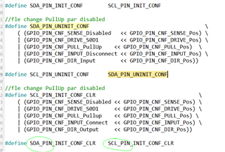
This LDO has an enable pin controlled by P0_23. Driving current is max 1uA so i configured my GPIO in S0S1 mode.

When i start my application i can control properly the LDO with this EN pin.

P0_23 = 0 -> LDO output =0V

P0_23 = 1 -> LDO output =2.6V (fixed output voltage of my reference).

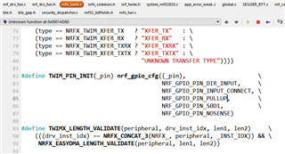
But a strange behavior happen when i init TWI module with: twi_init() .

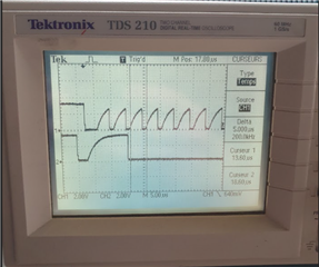
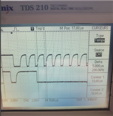
Once the line err_code = nrf_drv_twi_init(&m_twi, &twi_sensors_config, twi_handler, NULL); i executed, my LDO regulator voltage output goes to 1.7V.

Note that mu uC supply is 3.3V.

So i test to use twi_uninit() when i measure 1.7V, and magic, the LDO output goes low as if my TWI was controlling P0_23...

SCL and SDAZ are connected to the two NFC gpio that i disabled in the pre processor definition of the project. P0_10 and P_26.

The PIN_CNF of P0_23 doesn't change when i twi_init.

Is ther eany link that i missed somewhere between P0_23 and TWI module please ?

Thanks a lot

Parents
  • I'm also using externals pull up cause the 13kohm internal resistors are a bit weak. I disabled the internal resistor. I wonder if it is not the fact that when i init twi module the two lines are set to vbat and if the supply is not on, some electronic of the LDO pull the line to 1.7V. Solution will be may be to pull up to vcc of the nrf and not to the vdd of the ldo.

  • "my LDO regulator voltage output goes to 1.7V". Does this happen only when P0.23 = 0, ie the LDO is off? If so it is possible any output pins connected from the nRF52 to the sensor will power up the sensor through the sensor's internal schottky protection diodes and back-drive the LDO thus raising the LDO voltage from 0 to (say) 1.7 volts. If the only 2 pins connected to the sensor are SCL and SDAZ check the configuration after the init; if that is set to S0D1 or H0D1 with both pull-ups disabled then that would be unexpected behavior. Either pull-up enabled (or an external pull-up to nRF52 VDD) will phantom power the sensor and hence there will be a voltage on the LDO even when off.

  • Hi :)

    I removed my external pull up resitor and now i can see twi lines going to vcc of the nrf52. But i'm surprised of several things:

    My sensors i working well, i'm just not satisfied with the freqency and signal shape, and the pull up configuration

    1) here the content of the files nrf_drv_twi.c where Pull up are enable, but when i disable it, i see no difference on my physical lines, as if this config stuff were not used.

    2) i asked for 400khz but i only get 200khz on my scope, but it is ok in register.

    3) the shape of the rising edge is really slow.  on top it is with internal pull up resistor, i guess. Because as said earlier, when i disable it i get the same signal !

    Here is the signal with my external 4k7pull up resistors, and pull up resistors diable in the software...

  • Hi realised also that it is the twim module that is used and not the twi, so i found another place where pull up are defined

    So i disable it by using NRF_GPIO_PIN_NOPULL and now i clearly see the lines staying low without external resistor, so that was the line to modify.

    To confirm that i see in sdk_config :

    So it seems that TWIM is enabled but not TWIM0 and 1

    And TWI is also enable , not TWI0 but TWI1 yes.

    Frequency is set to 100khz on twi and twim , so the half of what i have on scope.

    i don't know how is managed twi vs twim because her eand ther ein the code i can see if twim is supported then, take this instead of twi module 

  • The example for sdk_config.h has this:

    	Line 148: #define NRFX_TWIM_ENABLED 1
    	Line 265: #define NRFX_TWI_ENABLED 1
    	Line 611: #define TWI_ENABLED 1
    	Line 657: #define TWI0_ENABLED 1
    	Line 671: #define TWI1_ENABLED 1

    Very confusing, don't remember just how these are used as I use bare metal drivers. Perhaps search for each of these to see how they are used.

    The frequency value you are using is not correct for 200kHz, if I get time I'll have a look at finding the correct value

  • Thanks  a lot for your help ;) in fct i would like 400khz but i only get 200khz.

    I don't know why this is so complicated , it should be simpler and much less confusing !

Reply Children
  • These are the figures I calculated, can't guarantee them but they are based on using the same algorithm used for the UART baud rate generator as the hardware peripherals are shared.

    // --------Calculated-------------------  --------Documentation--------
    // Required Register      Actual   Error  Register    Required   Actual
    // ======== =========== ======== =======  =========== ======== ========
    //  100000, 0x0199A000,  100006, +0.006%  0x01980000,  100000,  100000,
    //  200000, 0x03333000,  199996, -0.002%           -,       -,       -,
    //  250000, 0x04000000,  250000, +0.000%  0x04000000,  250000,  250000,
    //  400000, 0x06666000,  399993, -0.001%  0x06400000,  400000,  400000,

    This is the formula I used:

    #define MAGIC_SCALE_FACTOR 32
    #define MAGIC_SYSTEM_CLOCK 16000000ULL; // Typically 16MHz for Uart
    
    // Notes on calculation:
    uint32_t CalculatedRegisterValue;
    uint32_t ActualBaudRate = 250000UL;
       CalculatedRegisterValue = (uint32_t)((((uint64_t)RequiredBaudRate << MagicScaler) / SystemClock) + 0x800) & 0xFFFFF000;
       ActualBaudRate = (uint32_t)(((uint64_t)CalculatedRegisterValue * SystemClock) >> MagicScaler);

    The mask register may be different for the TWI/I2C with fewer active bits, haven't verified this.

    On the 'scope capture try checking with the sensor disconnected to ensure there are no external interactions which can affect the displayed waveform (eg clock-stretching etc).

Related