This discussion has been locked.
You can no longer post new replies to this discussion. If you have a question you can start a new discussion

Auto run on power up

I'm having some (minor) trouble with a board based on an NRF52840 that I want to start running as soon as power is applied... 

This is built using a RAK5010 board, but using custom firmware, the firmware uses an S340 softdevice.

Reading these forums it seems the general consensus is that once power is applied to the nrf52 then it should start executing, and the only similar discussions I could see were related to devices not being ready during power up and needing a delay or where the reset pin was incorrectly configured, neither is the case here.

The RAK5010 has an nrf52840 and a BG96 GPS module on board, the board has two switches one RST connected to the NRF reset pin (using pin 18) and a PWR connected to the BG96 chip. 

The behaviour I have is when power is applied nothing executes until the power button is used to turn on the BG96, at which point the NRF starts executing my code four seconds later.
On the schematic there's no connection from the power button to the NRF it is purely connected through the BG96, I can't see how/why any of the other connected pins would trigger the startup but clearly that must be the case.

So.... I wanted to understand the boot process and logic with a softdevice to try to work out if I have anything incorrectly configured during my install/flash that would be causing this and or what I can/or should change to fix this behaviour.


Is there any configuration that is flashed that can define what pins cause a startup? or alternatively is there any configuration that sets the board to *not* start executing unless a pin is toggled?

I can share my code since it will be opensource (albeit the full program is rather large) but I see this same behaviour if I compile any of the NRF SDK example program.

Parents
  • To find out if it's hardware or software related, I recommend to start with a simple blinky project: a short main() with init a gpio and turn ON a LED. Make sure to erase the nRF52840 first by for instance run 'nrfjprog --eraseall'. If the chip does not execute when power supply is applied, then you need to check that the schematic is followed and the voltage applied is within operating conditions (measure with an oscilloscope or multimeter). Make sure no gpio's are powered while supply voltage is not turned ON.

    Kenneth

  • Thanks for the tips, I'll experiment this evening. Unfortunately it's awkward to check all the pins directly since the RAK5010 is (understandably) quite tightly integrated on their board.
    So I'm still trying to understand from their schematic how powering up the BG96 would trigger the nRF52840 to boot. (the BG96 is only connected to nRF through GPIO pins using 2,3,6,7,8,11,26,27,28,29,30,31 - of those only 3,8,11,27,31 are the output lines)
    I'll put an oscilloscope on the pins I can get to and see if anything's going on and will try this with a clear firmware and a blinky app.

  • OK wiped everything completely, started with blinky which showed the same behaviour (dead until the BG96 was turned on) and I couldn't see any interesting voltage changes anywhere with the oscilloscope. so. wrote a small test program, that set those BG96 outputs as pulldown with interrupt and a log event:

    nrfx_gpiote_in_config_t in_config =
    NRFX_GPIOTE_CONFIG_IN_SENSE_TOGGLE(true);
    in_config.pull = NRF_GPIO_PIN_PULLDOWN;
    ...

    void in_pin_handler(nrfx_gpiote_pin_t pin, nrf_gpiote_polarity_t action)
    {
    bool set = nrfx_gpiote_in_is_set(pin);
    NRF_LOG_INFO("Pin %d - %d", pin, set);
    }

    while already running I turn the BG96 off, and then back on. When it starts up, there's a 4 second delay and then the following sequence of pin events:

    <info> app: Pin 31 - 1
    <info> app: Pin 8 - 1
    <info> app: Pin 11 - 0
    <info> app: Pin 11 - 1
    <info> app: Pin 27 - 1
    <info> app: Pin 11 - 1
    <info> app: Pin 11 - 1
    <info> app: Pin 27 - 0
    <info> app: Pin 27 - 1
    <info> app: Pin 27 - 0
    <info> app: Pin 27 - 1
    <info> app: Pin 27 - 0
    <info> app: Pin 27 - 1

    Is there any reason why any of those might trigger the nRF to start booting up?

  • Are you sure you don't have enabled pin reset by accident? There is no obvious reason why it should not start immediately.

    Kenneth

  • Power, clock and (optionally) reset is all that should be needed to start up. So unless the GPS module is controlling one of those then the nRF should start.

    The only other option I can think of is a bootloader that is programmed to wait for input from the GPS module. You did say you wiped everything, but is it possible that there is still a piece of code left that runs before your application?

  • Thanks and Kenneth going to give up for a bit! I just can't see it.

    I used mass_erase to start from a clean slate so I don't think that's related to old code, dumping the flash all appears to be gone when I start off.

    I'm pretty sure the reset pin is being set correctly, I tried with, firstly, reset disabled (i.e. 0xFFs in 0x10001200 and 0x1001204) then I tried a few other values (e.g. 31, 18 etc).

    This board has a reset button attached to pin 18, so if I don't set it or I set it to some other value then that button no longer resets the nRF, if I set it to 18 then the reset behaviour is as expected. So. I think it's being set and unset correctly and is being handled correctly.

    If I have it set to 18, then when the board is "off" (i.e. board has battery power but before the BG96 is started up) then pressing that reset button does nothing so I think this is a deeper issue. Once the BG96 is powered up, the nRF app boots up and the reset button behaves as expected.

    Hence my first questions if there was anything else that controls this or could be causing this since I couldn't see anything in the documentation and it sounds from your answers like that isn't the case.

    All very odd and I can't figure it out at the moment. Not a show stopper, I can live with having to start up with the BG96 button, and unless it's not complete the RAK5010 schematic doesn't show any reason why this might happen.

    If I can find a way to get to the power and clock lines somewhere I'll have a go at monitoring those at some point.

    thanks again.

  • I am not aware of anything, so monitoring power lines I think is a good idea. There is some requirements to the rise up time on VDD that you can check at the same time:
    https://infocenter.nordicsemi.com/topic/ps_nrf52840/recommended_op_conditions.html 

Reply Children
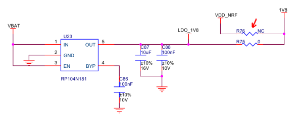
  • Perfect! thanks for the tip/documentation link. I used that to follow and check the power lines and check the RAK schematic, the VDD1 line wasn't receiving 1.8v until the BG96 powered up, but oddly I saw they had a non-installed jumper to supply this on their schematic. If I add a jumper here (it's a 0ohm) then the behaviour is as expected and the nRF powers up on battery connection.

Related