
I am using the following code to generate and output a n-MHz clock on a GPIO pin. (code is borrowed/copied from another question on this forum)
    /*Start HF crystal for improved clock tolerance*/
    NRF_CLOCK->TASKS_HFCLKSTART = 1;
    while (NRF_CLOCK->EVENTS_HFCLKSTARTED == 0);

    NRF_TIMER2->PRESCALER = 0; // 16MHz
    NRF_TIMER2->SHORTS = TIMER_SHORTS_COMPARE0_CLEAR_Msk;
    NRF_TIMER2->CC[0] = 1;

    NRF_GPIOTE->CONFIG[0] = GPIOTE_CONFIG_MODE_Task | (CAMERA_XCLK_PIN << GPIOTE_CONFIG_PSEL_Pos) |
                            (GPIOTE_CONFIG_POLARITY_Toggle << GPIOTE_CONFIG_POLARITY_Pos);

    /*Connect TIMER event to GPIOTE out task*/
    NRF_PPI->CH[0].EEP = (uint32_t) &NRF_TIMER2->EVENTS_COMPARE[0];
    NRF_PPI->CH[0].TEP = (uint32_t) &NRF_GPIOTE->TASKS_OUT[0];
    NRF_PPI->CHENSET   = 1;

    /*Starts clock signal*/
    NRF_TIMER2->TASKS_START = 1;
However, the clock output I get is very inconsistent:

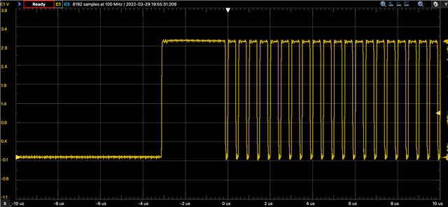
In addition to the output frequency and duty cycle being all over the place, in the brief periods where it looks like a real clock, the frequency is 4 MHz, though it's expected to be 16 or 8 MHz. This is running on an Arduino Nano 33 BLE nRF52840 without the Arduino framework, no softdevice, no RTOS (bare-metal via SWD). Where is a good place to being troubleshooting? What could cause the PPI to miss a timer event, or the GPIOTE to skip its task?
Thank you,
Sebastian
