AOA: Antenna switch pattern and IQ sampling via nrf52833

Hi! 

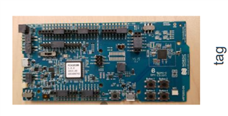
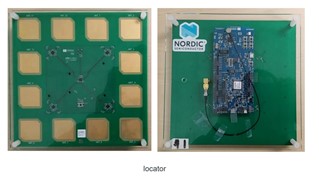
I'm working on direction finding. I'm using a nrf52833dk as a beacon, a nrf52833dk and a Direction Finding Antenna Board (PCA2005) as a locator for a bluetooth direction finding AOA development. as follows:


The SDK I am using is NCS 1.7.1, the toolchain is SEGGER Embedded Studio (SES), examples are “direction_finding_connectionless_tx” and “direction_finding_connectionless_rx”.

For the beacon, I added “CONFIG_BT_CTLR_DF_ANT_SWITCH_TX=n” in “prj.conf” to make it work in AOA mode.

For the locator, since a 12-antenna array is used, the GPIOs I use are P0.03, P0.04, P0.28, P0.29, and the antenna pattern is configured in “main.c” as follows:

static const uint8_t ant_patterns[] = { 0x2, 0x0, 0x5, 0x6, 0x1, 0x4,
					0xC, 0x9, 0xE, 0xD, 0x8, 0xA };

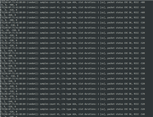
And, I made some modifications in the cte_recv_cb() function to print the IQ data.

Now I have the following problems:

    1、I placed the locator obliquely above the beacon to sample several sets of IQ sampling data, and calculated the phase and peak amplitude according to formula

  • Amplitude = sqrt(pow(I,2)+pow(Q,2))
  • Phase = arctan(Q/I),

but the I and Q values are different from the sinusoidal signal. The following is one of the sets of data:


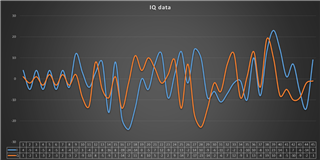
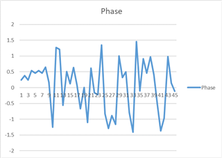
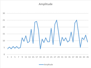
I would like to ask: Is there a problem with the I and Q values?

If there is a problem, where did it go wrong and how should it be improved? If there is no problem, why is the IQ value far from the sine wave?

    2、In these two examples, are there any parameters corresponding to the current sampling antenna ID? Because I want to know which antenna a pair of IQ values corresponds to, and use this to calculate AOA.

I need a little help to put all this fine.

Regards,

John

Parents
  • Hello all, I'm exactly at same point as @John. Currently I'm printing the IQ data, however I tried to find any info about the antenna ID that produces each IQ data but I didn't get any success until the moment (looking for the bt_df_conn_iq_samples_report struct, I tried to print the parameter  rssi_ant_id but the value is allways "2", and in fact I'm using 4 linear antennas from the 12 available on the antenna). Another question that maybe you can help me, based on literature people advise to use external algorithms to decode the sampled data and return an angle, many suggest the MUSIC algorithm, but I didn't find many samples on the internet, or at least any sample easy to implement with the returned data from the devkit, where can I find it? 

    Best regards, and thank you for your help!

    Miguel Soares

  • So for the sequence of the antennas, check the table for the antenna pattern and the description in the white paper. The pattern is deterministic so there should be no need to read back the antenna port, this can be calculated instead.

Reply Children
  • Hello PaKa, thank you for your prompt reply.

    I'm sorry but I still confused. First thing, according to the project configuration I'm using a 2us slot time, which means a switch(2us)+sample(2us)=switching_space(4us). I used a logic analyser and in fact, the mux control IOs are changing with a period of 4us, so I assume the configuration is ok. However here comes my first doubt, from my understanding till the moment about AoA, I should receive a IQ sample for each antenna, but what the example plots is just one IQ sample (sometimes based in 45 samples or 1 sample, check the logs bellow). So, how can I despite from each antenna came that precise IQ sample?

  • For each correctly received package you will get an array of IQ values. The amount of IQ values you get will depend on the length of the CTE event. The standard setting for the example should be 160µs CTE event. This will give you 45 samples (https://infocenter.nordicsemi.com/topic/nwp_036/WP/nwp_036/sample_buffer_config.html). This is 8 values for the reference period and then 37 values from the different antennas in the array (you loop more than once through the pattern with the 160µs CTE period).

    The IQ values are stored in a RAM array by the Controller Subsystem, you will need to fetch it to use it in the application space to calculate the angles.Remember these values comes as pairs, one I value and one Q value for each sample. These are signed chars (Bluetooth standard have these as 8 bit values so they are rounded down from the raw radio values).

    The sequence for the antenna switching is as given in the PS, https://infocenter.nordicsemi.com/topic/ps_nrf52833/radio.html?cp=4_1_0_5_17_11_5#concept_dfe_antenna_switching. In the default code example we have the 12 antennas and then you will cycle through all entries in the table and then restart from entry 3 and loop like this until the entire CTE period is over.

    Note: to be Bluetooth SIG compliant you should always loop through the reference antenna when you loop the pattern. To do this, add the reference antenna also as the last antenna in the pattern.

  • Hi PaKa,

    I have read the chapter`NCS -> Antenna Pattern and using ISP1907 Angle of Arrival Demo Kit but still be confused.

    Antenna

    PATTERN[3:0]

    ANT_12

    0 (0b0000)

    ANT_10

    1 (0b0001)

    ANT_11

    2 (0b0010)

    RFU

    3 (0b0011)

    ANT_3

    4 (0b0100)

    ANT_1

    5 (0b0101)

    ANT_2

    6 (0b0110)

    RFU

    7 (0b0111)

    ANT_6

    8 (0b1000)

    ANT_4

    9 (0b1001)

    ANT_5

    10 (0b1010)

    RFU

    11 (0b1011)

    ANT_9

    12 (0b1100)

    ANT_7

    13 (0b1101)

    ANT_8

    14 (0b1110)

    RFU

    15 (0b1111)

    From the table, every ANT# should map a pattern:

    // setting 1
    // 11,12,1,2,3,4,5,6,7,8,9,10
    static const uint8_t ant_patterns[] = {0x2, 0x0, 0x5, 0x6, 0x1, 0x4,
    									   0xC, 0x9, 0xE, 0xD, 0x8, 0xA};
    // why not the following: 
    // setting 1
    // 11,12,1,2,3,4,5,6,7,8,9,10
    static const uint8_t ant_patterns[] = {0x2, 0x0, 0x5, 0x6, 0x4, 0x9,
    									   0xA, 0x8, 0xD, 0xE, 0xC, 0x1};

    // setting 2
    // 11,12,1,2,10,3,9,4,8,7,6,5
    static const uint8_t ant_patterns[] = {0x2, 0x0, 0x5, 0x6, 0x4, 0x9,
    									   0xA, 0x8, 0xD, 0xE, 0xC, 0x1};
    // why not the following: 
    // setting 2
    // 11,12,1,2,10,3,9,4,8,7,6,5
    static const uint8_t ant_patterns[] = {0x2, 0x0, 0x5, 0x6, 0x1, 0x4,
    									   0xC, 0x9, 0xE, 0xD, 0x8, 0xA};

  • Did you check this in nRF Connect SDK master? I believe there may have been a mistake in the antenna selection table.

  • I checked this in version 1.9, what's the currect antenna table do you think ?

Related