Hi!
I'm working on direction finding. I'm using a nrf52833dk as a beacon, a nrf52833dk and a Direction Finding Antenna Board (PCA2005) as a locator for a bluetooth direction finding AOA development. as follows:
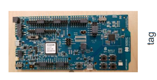
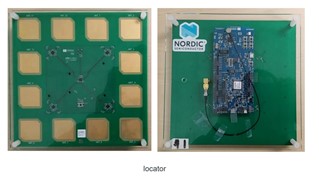
The SDK I am using is NCS 1.7.1, the toolchain is SEGGER Embedded Studio (SES), examples are “direction_finding_connectionless_tx” and “direction_finding_connectionless_rx”.
For the beacon, I added “CONFIG_BT_CTLR_DF_ANT_SWITCH_TX=n” in “prj.conf” to make it work in AOA mode.
For the locator, since a 12-antenna array is used, the GPIOs I use are P0.03, P0.04, P0.28, P0.29, and the antenna pattern is configured in “main.c” as follows:
static const uint8_t ant_patterns[] = { 0x2, 0x0, 0x5, 0x6, 0x1, 0x4,
					0xC, 0x9, 0xE, 0xD, 0x8, 0xA };
And, I made some modifications in the cte_recv_cb() function to print the IQ data.
Now I have the following problems:
1、I placed the locator obliquely above the beacon to sample several sets of IQ sampling data, and calculated the phase and peak amplitude according to formula
- Amplitude = sqrt(pow(I,2)+pow(Q,2))
- Phase = arctan(Q/I),
but the I and Q values are different from the sinusoidal signal. The following is one of the sets of data:
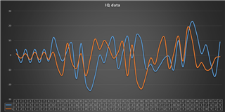
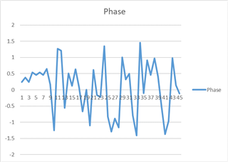
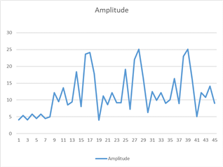
I would like to ask: Is there a problem with the I and Q values?
If there is a problem, where did it go wrong and how should it be improved? If there is no problem, why is the IQ value far from the sine wave?
2、In these two examples, are there any parameters corresponding to the current sampling antenna ID? Because I want to know which antenna a pair of IQ values corresponds to, and use this to calculate AOA.
I need a little help to put all this fine.
Regards,
John


