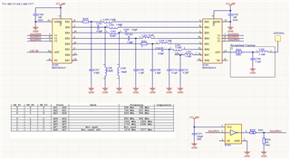
At first glance it looks very similar to the configuration on the Thingy:91, but there is one important difference and that is that the RX-pins on the SP8T switches aren't connected to each other in the same way, which if I'm understanding correctly they need to be when you're using the same three control signals on both switches.
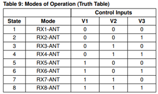
If all three control signals are 0, RX1 will be connected to ANT on both switches, but you have RX1 connected to RX2 and vice versa.
So while ANT and RX1 are connected on IC300, you need RX2 and ANT connected on IC301 to have a signal go to the actual antenna ANT300A. Correct me if I'm wrong, but using the same three control signals on both switches makes this configuration not work.
Two other comments:
1. All components between the two switches need to be adjusted/tuned. The antenna manufacturer can probably help with this.
2. You also need an LNA between the nRF9160 and the GPS input to the antenna, this might be on a separate part of the schematic that I can't see but I thought I'd mention it.