nrf52840 Vbus supply and supplying external components with 3.3v

I am using the nrf52840 on the Raytac MDBT50Q-1MV2 module. (https://www.raytac.com/product/ins.php?index_id=24)

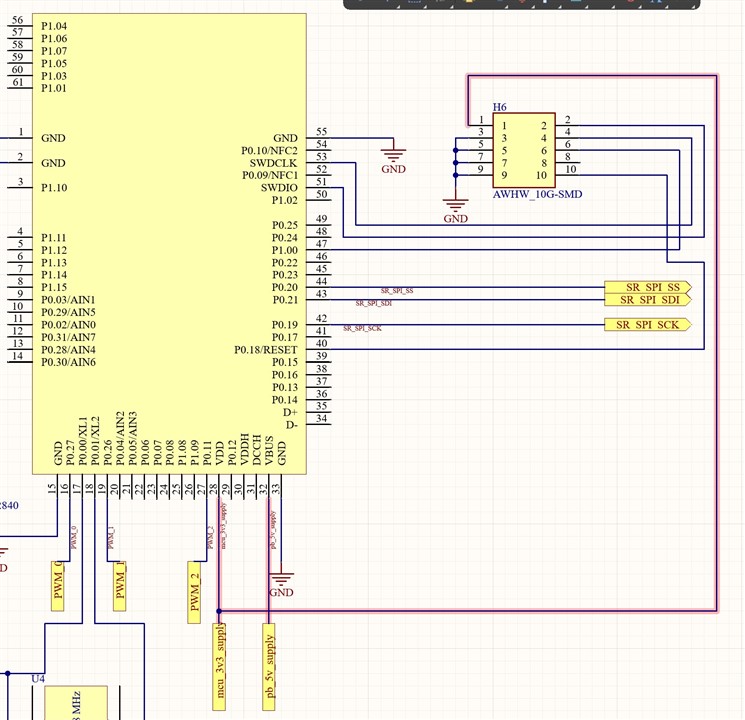
I am supplying the module with 5v USB power to the VBUS pin. I need a standard 3v3 output from the module to power external components and I am using VDD for this purpose. However, when I provide power to the chip the VDD is not outputting 3v3. What setup do I need in order to get a 3v3 output from the module/chip in order to supply external components?

Thank you.

Parents Reply Children
  • Hi,

    Can you share the schematics for your design?

    regards

    Jared 

  • Hi,

    this is the relevant schematic. We are now getting a 4.4v output from VDD. We untied VDDH and VBUS so we are not sure what is producing this 4.4v voltage. Our measured input to VBUS currently is 5.2V. This 4.4V is not ideal but still usable for our system. However, when we try to program the board with a j-link connection through the header H6, we are getting an error on our nrfprog runner.

    Error code 18 is: WrongFamilyForDeviceError

    And this error is stopping us from being able to program our board.

    Thank you.

  • Hi,

    I

    Callum Little said:
    We are now getting a 4.4v output from VDD. We untied VDDH and VBUS so we are not sure what is producing this 4.4v voltage. Our measured input to VBUS currently is 5.2V. This 4.4V is not ideal but still usable for our system.

    Strange, What voltage do you measure on VDDH when you untie VDDH and VBUS? Can you double check that the power tracks aren't shorted on your PCB? 

    Callum Little said:
    However, when we try to program the board with a j-link connection through the header H6, we are getting an error on our nrfprog runner.

    Most likely, this is a consequence of the nRF not being supplied correctly. 

    regards

    Jared

  • Hi,

    I assume the j-link connection is due to the nRF supply error.

    Due to our current PCB setup and the qfn package of the nrf module, we are unable to directly probe the VDDH pin. I am double-checking the soldering setup today to make sure there are no shorts.

    Are you aware of any configurations that may cause a 4.4v voltage on the VDD pin?

    And what configuration should we have in order to get 0v on VDD so that we can supply our 3.3v to that pin in order to power the board?

    Thank you,

    -Also apologies for the duplicate tickets

  • Callum Little said:
    Are you aware of any configurations that may cause a 4.4v voltage on the VDD pin?

    No, if the nRF52840 is used in High Voltage Mode which sets VDD as an output for external supply, then the maximum VDD can be set to is 3V3. 

    Callum Little said:

    And what configuration should we have in order to get 0v on VDD so that we can supply our 3.3v to that pin in order to power the board?

    If you want to power the nRF52840 directly through VDD (Normal Mode), then you have to tie VDDH and VDD together, which will set VDD as an Input. Maximum Input voltage is then 3V6.

    regards

    Jared

Related