Radio test example - UART pins

Hey there,

We are working with NRF52832 WLSCP package,

We had stated certification process , for BQB testing need to use the Radio test example with UART between EUT to the PC ( using a dongle or SDK)

As my new design does not use all required GPIO, Idon't have direct connection to connect UART pins

1. Is there a way to do the UART over BLE?

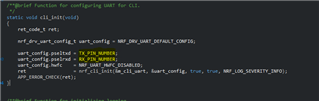
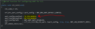
2. How to change the pins to fit my accessible GPIO's?

Default GPIO nRF52832

UART nRF52832

Interface MCU UART


P0.05

RTS

CTS

P0.07

P0.06

TXD

RXD

P0.08

P0.07

CTS

RTS

P0.05

P0.08

RXD

TXD

P0.06

Parents
  • actually, the difficulty is how to redefine the pins..... as it is not clear from the example.. 

    regard sdk in the website only version 17 is available for download

  • You are using the nrf52832 WLCSP, and you want to use P0.07, P0.08, P0.05 and P0.06 as the UART pins ?

    Are you more familiar with the nRF5 SDK or the nRF Connect SDK ?

    In the nRF5SDK you can do it in the main file, if you build for the PCA10040 it will be for the 52832.
     

    In nRF Connect SDK you have to create a overlay file for the new pins you want to use.

    See example in this devzone ticket

    &uart0 {
    compatible = "nordic,nrf-uart";
    status = "okay";
    current-speed = <115200>;
    tx-pin = <6>;
    rx-pin = <8>;
    /delete-property/ rts-pin;
    /delete-property/ cts-pin;
    };

    Here is a link to zephyr overlay, Devicetree HOWTOs — Zephyr Project Documentation 

    Regards,
    Jonathan

  • on top of this regard doing it using segger is there a clear application note , as the ticket is not clear...

    RX TX testing is mandatory for regulation purposes... and guidance is required to be provided to the lab.

    Simply need clear and simple instructions ....which are working...


  • In the nRF5 SDK v17.1.0 that you presume you have downloaded, you will find the pin number as defined like the picture above. 

    You can change the "TX_PIN_NUMBER" and "RX_PIN_NUMBER" to the pins you need to use in your layout. You only need to edit the two instances to P0.06 and P0.08

    Regards,
    Jonathan

  • Well this is not good enough as this is Only UART pins,I got inputs that pins are defined in h file

    and also need to define ALL the 4 pins required not only rx tx

  • /**
    * Copyright (c) 2014 - 2021, Nordic Semiconductor ASA
    *
    * All rights reserved.
    *
    * Redistribution and use in source and binary forms, with or without modification,
    * are permitted provided that the following conditions are met:
    *
    * 1. Redistributions of source code must retain the above copyright notice, this
    * list of conditions and the following disclaimer.
    *
    * 2. Redistributions in binary form, except as embedded into a Nordic
    * Semiconductor ASA integrated circuit in a product or a software update for
    * such product, must reproduce the above copyright notice, this list of
    * conditions and the following disclaimer in the documentation and/or other
    * materials provided with the distribution.
    *
    * 3. Neither the name of Nordic Semiconductor ASA nor the names of its
    * contributors may be used to endorse or promote products derived from this
    * software without specific prior written permission.
    *
    * 4. This software, with or without modification, must only be used with a
    * Nordic Semiconductor ASA integrated circuit.
    *
    * 5. Any software provided in binary form under this license must not be reverse
    * engineered, decompiled, modified and/or disassembled.
    *
    * THIS SOFTWARE IS PROVIDED BY NORDIC SEMICONDUCTOR ASA "AS IS" AND ANY EXPRESS
    * OR IMPLIED WARRANTIES, INCLUDING, BUT NOT LIMITED TO, THE IMPLIED WARRANTIES
    * OF MERCHANTABILITY, NONINFRINGEMENT, AND FITNESS FOR A PARTICULAR PURPOSE ARE
    * DISCLAIMED. IN NO EVENT SHALL NORDIC SEMICONDUCTOR ASA OR CONTRIBUTORS BE
    * LIABLE FOR ANY DIRECT, INDIRECT, INCIDENTAL, SPECIAL, EXEMPLARY, OR
    * CONSEQUENTIAL DAMAGES (INCLUDING, BUT NOT LIMITED TO, PROCUREMENT OF SUBSTITUTE
    * GOODS OR SERVICES; LOSS OF USE, DATA, OR PROFITS; OR BUSINESS INTERRUPTION)
    * HOWEVER CAUSED AND ON ANY THEORY OF LIABILITY, WHETHER IN CONTRACT, STRICT
    * LIABILITY, OR TORT (INCLUDING NEGLIGENCE OR OTHERWISE) ARISING IN ANY WAY OUT
    * OF THE USE OF THIS SOFTWARE, EVEN IF ADVISED OF THE POSSIBILITY OF SUCH DAMAGE.
    *
    */
    #ifndef PCA10040_H
    #define PCA10040_H

    #ifdef __cplusplus
    extern "C" {
    #endif

    #include "nrf_gpio.h"

    // LEDs definitions for PCA10040
    #define LEDS_NUMBER 4

    #define LED_START 17
    #define LED_1 17
    #define LED_2 18
    #define LED_3 19
    #define LED_4 20
    #define LED_STOP 20

    #define LEDS_ACTIVE_STATE 0

    #define LEDS_INV_MASK LEDS_MASK

    #define LEDS_LIST { LED_1, LED_2, LED_3, LED_4 }

    #define BSP_LED_0 LED_1
    #define BSP_LED_1 LED_2
    #define BSP_LED_2 LED_3
    #define BSP_LED_3 LED_4

    #define BUTTONS_NUMBER 4

    #define BUTTON_START 13
    #define BUTTON_1 13
    #define BUTTON_2 14
    #define BUTTON_3 15
    #define BUTTON_4 16
    #define BUTTON_STOP 16
    #define BUTTON_PULL NRF_GPIO_PIN_PULLUP

    #define BUTTONS_ACTIVE_STATE 0

    #define BUTTONS_LIST { BUTTON_1, BUTTON_2, BUTTON_3, BUTTON_4 }

    #define BSP_BUTTON_0 BUTTON_1
    #define BSP_BUTTON_1 BUTTON_2
    #define BSP_BUTTON_2 BUTTON_3
    #define BSP_BUTTON_3 BUTTON_4

    #define RX_PIN_NUMBER 31 //8
    #define TX_PIN_NUMBER 2 //6
    #define CTS_PIN_NUMBER 3 //7
    #define RTS_PIN_NUMBER 5
    #define HWFC true

    #define SPIS_MISO_PIN 28 // SPI MISO signal.
    #define SPIS_CSN_PIN 12 // SPI CSN signal.
    #define SPIS_MOSI_PIN 25 // SPI MOSI signal.
    #define SPIS_SCK_PIN 29 // SPI SCK signal.

    #define SPIM0_SCK_PIN 29 // SPI clock GPIO pin number.
    #define SPIM0_MOSI_PIN 25 // SPI Master Out Slave In GPIO pin number.
    #define SPIM0_MISO_PIN 28 // SPI Master In Slave Out GPIO pin number.
    #define SPIM0_SS_PIN 12 // SPI Slave Select GPIO pin number.

    #define SPIM1_SCK_PIN 6 //2 // SPI clock GPIO pin number.
    #define SPIM1_MOSI_PIN 3 // SPI Master Out Slave In GPIO pin number.
    #define SPIM1_MISO_PIN 4 // SPI Master In Slave Out GPIO pin number.
    #define SPIM1_SS_PIN 5 // SPI Slave Select GPIO pin number.

    #define SPIM2_SCK_PIN 12 // SPI clock GPIO pin number.
    #define SPIM2_MOSI_PIN 13 // SPI Master Out Slave In GPIO pin number.
    #define SPIM2_MISO_PIN 14 // SPI Master In Slave Out GPIO pin number.
    #define SPIM2_SS_PIN 15 // SPI Slave Select GPIO pin number.

    // serialization APPLICATION board - temp. setup for running serialized MEMU tests
    #define SER_APP_RX_PIN 23 // UART RX pin number.
    #define SER_APP_TX_PIN 24 // UART TX pin number.
    #define SER_APP_CTS_PIN 2 // UART Clear To Send pin number.
    #define SER_APP_RTS_PIN 25 // UART Request To Send pin number.

    #define SER_APP_SPIM0_SCK_PIN 27 // SPI clock GPIO pin number.
    #define SER_APP_SPIM0_MOSI_PIN 2 // SPI Master Out Slave In GPIO pin number
    #define SER_APP_SPIM0_MISO_PIN 26 // SPI Master In Slave Out GPIO pin number
    #define SER_APP_SPIM0_SS_PIN 23 // SPI Slave Select GPIO pin number
    #define SER_APP_SPIM0_RDY_PIN 25 // SPI READY GPIO pin number
    #define SER_APP_SPIM0_REQ_PIN 24 // SPI REQUEST GPIO pin number

    // serialization CONNECTIVITY board
    #define SER_CON_RX_PIN 24 // UART RX pin number.
    #define SER_CON_TX_PIN 23 // UART TX pin number.
    #define SER_CON_CTS_PIN 25 // UART Clear To Send pin number. Not used if HWFC is set to false.
    #define SER_CON_RTS_PIN 2 // UART Request To Send pin number. Not used if HWFC is set to false.


    #define SER_CON_SPIS_SCK_PIN 27 // SPI SCK signal.
    #define SER_CON_SPIS_MOSI_PIN 2 // SPI MOSI signal.
    #define SER_CON_SPIS_MISO_PIN 26 // SPI MISO signal.
    #define SER_CON_SPIS_CSN_PIN 23 // SPI CSN signal.
    #define SER_CON_SPIS_RDY_PIN 25 // SPI READY GPIO pin number.
    #define SER_CON_SPIS_REQ_PIN 24 // SPI REQUEST GPIO pin number.

    #define SER_CONN_CHIP_RESET_PIN 11 // Pin used to reset connectivity chip


    // Arduino board mappings
    #define ARDUINO_SCL_PIN 27 // SCL signal pin
    #define ARDUINO_SDA_PIN 26 // SDA signal pin
    #define ARDUINO_AREF_PIN 2 // Aref pin
    #define ARDUINO_13_PIN 25 // Digital pin 13
    #define ARDUINO_12_PIN 24 // Digital pin 12
    #define ARDUINO_11_PIN 23 // Digital pin 11
    #define ARDUINO_10_PIN 22 // Digital pin 10
    #define ARDUINO_9_PIN 20 // Digital pin 9
    #define ARDUINO_8_PIN 19 // Digital pin 8

    #define ARDUINO_7_PIN 18 // Digital pin 7
    #define ARDUINO_6_PIN 17 // Digital pin 6
    #define ARDUINO_5_PIN 16 // Digital pin 5
    #define ARDUINO_4_PIN 15 // Digital pin 4
    #define ARDUINO_3_PIN 14 // Digital pin 3
    #define ARDUINO_2_PIN 13 // Digital pin 2
    #define ARDUINO_1_PIN 12 // Digital pin 1
    #define ARDUINO_0_PIN 11 // Digital pin 0

    #define ARDUINO_A0_PIN 7 //3 // Analog channel 0
    #define ARDUINO_A1_PIN 4 // Analog channel 1
    #define ARDUINO_A2_PIN 28 // Analog channel 2
    #define ARDUINO_A3_PIN 29 // Analog channel 3
    #define ARDUINO_A4_PIN 30 // Analog channel 4
    #define ARDUINO_A5_PIN 8 //31 // Analog channel 5


    #ifdef __cplusplus
    }
    #endif

    #endif // PCA10040_H

  • PCA10040.h i changes as follows, currently still having issues ...

Reply Children
Related