
Hello,
I just received an nRF21540 EK, I am trying to use it on my current hardware which is only for scanning beacons (won't transmit) so need use it as LNA in the received path 100% of the time after initializid the FEM.
I read the documentation at https://infocenter.nordicsemi.com/pdf/nRF21540_PS_v1.2.pdf
All the steps below are for testing purposes before implementing any driver or dirtying my hands on the software side
Configuring it using the GPIO pins
I put it directly to ground:
TX_EN to GND
MOSI to GND
SPI clock (SCK) to GND
ANT1 (to use ANT1)
Mode to GND(which is supposed won't affect RX, just won't let it be unconnected)
Pins I changed state using a Switch
PDN, originally in low state then switch to VDD)
RX_EN, originally in low state then switch to VDD after PDN)
Pins to VDD or unconnected
CSN to VDD (Connect to VDD if SPI interface is not used)
MISO, unconnected
and following this diagram:
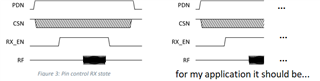
From my understanding, the timing is just to allow the nRF21540 to set the correct state, to let it change from Power-Down to Program mode, and after it is in program mode I can set it to Receive using RX_EN.
But for some reason using the nRF21540 with the steps above is returns and lower detection of beacons on my end (even a lower RSSI), and I want to make sure the configuration I am using is right (besides, I am not using a driver to control it, just GPIO configuration set manually the states from PDN and RX_EN with switches)
I connected the nRF21540 K using u.FL connector to SMA and for the RX path, and for the ANT1 connector I am using an antenna with SMA connector
Can you provide some insight?
Regards,


