This discussion has been locked.
You can no longer post new replies to this discussion. If you have a question you can start a new discussion

Custom GPIO pin in Overlay file

I want to add a simple GPIO pin that act as output pin, in the peripheral_uart example .
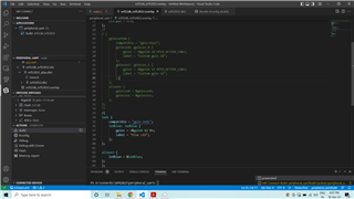
in main.c
#include <drivers/gpio.h>
//#define GPIO0_LABEL DT_PROP(DT_NODELABEL(gpiocus0), label)
//#define GPIO0_STATUS DT_PROP(DT_NODELABEL(gpiocus0), status)
//#define PIN 10
//#define FLAGS 0
#define LEDBLUE_NODE DT_ALIAS(ledblue)
#define LEDBLUE      DT_GPIO_LABEL(LEDBLUE_NODE, gpios)
#define LEDBLUEPIN   DT_GPIO_PIN(LEDBLUE_NODE, gpios)
#define FLAGS        DT_GPIO_FLAGS(LEDBLUE_NODE, gpios)
added these line main()
{
 const struct device *dev;
    bool led_is_on = true;
    int ret;
   
    dev = device_get_binding(LEDBLUE);
    ret = gpio_pin_configure(devLEDBLUEPINGPIO_OUTPUT_ACTIVE | FLAGS);


    for (;;) {
        dk_set_led(RUN_STATUS_LED, (++blink_status) % 2);
        k_sleep(K_MSEC(RUN_LED_BLINK_INTERVAL));

         gpio_pin_set(devLEDBLUEPIN1);//(dev, LEDBLUEPIN, (int)led_is_on);
        led_is_on = !led_is_on;
        k_msleep(500);
                printk("hello2");
    }
I could not see any change in the GPIO pin.
I have tried followed the below links,
https://stackoverflow.com/questions/69873229/how-to-add-constants-to-a-devicetree-overlay
So, kindly show me any simple method to just turn on a GPIO and Read a pin from a GPIO by the way of OVERLAY FILE.
Parents
  • Hi,


    Are you using a development kit?

    How are you checking if the signal is toggling? Do you measure the voltage directly on the pin?

    Can you try to use GPIO_ACTIVE_LOW instead 0 in the project config.

    regards

    Jared 

  • Thank you very much...its working.  DT_ALIAS setting configured properly; then starts working. In Prj.conf , i have only this line  CONFIG_GPIO=y.

    when writing a pin, 

        dev = device_get_binding(LED1);
        if (dev == NULL) {
            return;
        }

        ret = gpio_pin_configure(dev, PIN1, GPIO_OUTPUT_ACTIVE | FLAGS);
        if (ret < 0) {
            return;
        }
    gpio_pin_set(dev, PIN1, 1);// when PIN=1; in the output voltage we get 0V, when PIN=0; we get 3.3Voltage in that

    And also in reading a pin; 

        dev = device_get_binding(BUTT);
        if (dev == NULL) {
            return;
        }

    ret = gpio_pin_configure(dev, PIN2, GPIO_INPUT| FLAGS);
    static int8_t readPinVal=0;
    readPinVal = gpio_pin_get(dev, PIN2); // when PIN2 =0; We get readPinVal =1; and vice versa.
    I do want in in reversal. How to do that.
    HOW TO USE THIS:
    arduino_header: connector {
            compatible = "arduino-header-r3";
            #gpio-cells = <2>;
            gpio-map-mask = <0xffffffff 0xffffffc0>;
            gpio-map-pass-thru = <0 0x3f>;
            gpio-map = <0 0 &gpio0 3 0>,    /* A0 */
                   <1 0 &gpio0 4 0>,    /* A1 */
                   <2 0 &gpio0 28 0>,   /* A2 */
    in the overlay file, in-order to act this pin as input or output.
Reply
  • Thank you very much...its working.  DT_ALIAS setting configured properly; then starts working. In Prj.conf , i have only this line  CONFIG_GPIO=y.

    when writing a pin, 

        dev = device_get_binding(LED1);
        if (dev == NULL) {
            return;
        }

        ret = gpio_pin_configure(dev, PIN1, GPIO_OUTPUT_ACTIVE | FLAGS);
        if (ret < 0) {
            return;
        }
    gpio_pin_set(dev, PIN1, 1);// when PIN=1; in the output voltage we get 0V, when PIN=0; we get 3.3Voltage in that

    And also in reading a pin; 

        dev = device_get_binding(BUTT);
        if (dev == NULL) {
            return;
        }

    ret = gpio_pin_configure(dev, PIN2, GPIO_INPUT| FLAGS);
    static int8_t readPinVal=0;
    readPinVal = gpio_pin_get(dev, PIN2); // when PIN2 =0; We get readPinVal =1; and vice versa.
    I do want in in reversal. How to do that.
    HOW TO USE THIS:
    arduino_header: connector {
            compatible = "arduino-header-r3";
            #gpio-cells = <2>;
            gpio-map-mask = <0xffffffff 0xffffffc0>;
            gpio-map-pass-thru = <0 0x3f>;
            gpio-map = <0 0 &gpio0 3 0>,    /* A0 */
                   <1 0 &gpio0 4 0>,    /* A1 */
                   <2 0 &gpio0 28 0>,   /* A2 */
    in the overlay file, in-order to act this pin as input or output.
Children
No Data
Related