Power I2C Device through GPIO

Hi, 

I have builded a circuit with a nRF52DK and a mpu9250 IMU. If I power the Sensor with VDD the Zephyr driver and all of the Software performs well and the values from the IMU are displayed correctly in my console. 
Now I have Problems with powering the mpu sensor through the nRF's GPIOs. My first attempt is to set the GPIO_0 to HIGH and bind the mpu with a little delay. I think i had tenable and disable some driver for the TWI bus, but until now I have not found the right way. Maybe you can give me some advise. 
nrf Connect SDK 1.9.1 - VSCode 

	const struct device *gpio_dev1;
	gpio_dev1 = device_get_binding("GPIO_0");

	if (!gpio_dev1) {
		printk("Cannot find %s!\n", "GPIO_0");
		return;
	}

	ret = gpio_pin_configure(gpio_dev1, VDD_PIN1, GPIO_OUTPUT_ACTIVE);	
	if (ret < 0) {
		return;
	}

	gpio_pin_set(gpio_dev1, VDD_PIN1, 1);
	NRFX_DELAY_US(MEASURE_INTERVAL*1000); // 2 Seconds

	const char *const label = DT_LABEL(DT_INST(0, DEVICE_NAME_IMU)); //DEVICE_NAME_IMU = invensense_mpu9250
	const struct device *mpu9250 = device_get_binding(label);
	if (!mpu9250) {
		printf("Failed to find sensor %s\n", label);
		//return;
	}else{
		printk("Sensor connected: %s\n", label);
	}

Console Output: 

[00:00:02.048,858] <inf> sdc_hci_driver: SoftDevice Controller build revision: 
                                         0e e7 c5 66 67 18 3c ac  b3 d2 cc 81 a3 dc f1 c0 |...fg.<. ........
                                         c0 36 02 22                                      |.6."             
[00:00:02.051,208] <inf> bt_hci_core: HW Platform: Nordic Semiconductor (0x0002)
[00:00:02.051,208] <inf> bt_hci_core: HW Variant: nRF52x (0x0002)
[00:00:02.051,208] <inf> bt_hci_core: Firmware: Standard Bluetooth controller (0x00) Version 14.50663 Build 1008232294
[00:00:02.052,124] <inf> bt_hci_core: Identity: EF:F0:9B:1E:C2:0B (random)
[00:00:02.052,154] <inf> bt_hci_core: HCI: version 5.2 (0x0b) revision 0x12fe, manufacturer 0x0059
[00:00:02.052,154] <inf> bt_hci_core: LMP: version 5.2 (0x0b) subver 0x12fe
[00:00:02.092,163] <err> i2c_nrfx_twi: Error 0x0BAE0001 occurred for message 0
[00:00:02.092,163] <err> MPU9250: Failed to read data sample.
[0:00:04.102]:2942.578125 mV
[0:00:04.117]:23.3 Cel
[0:00:04.131]:1003 hPa
sample fetch/get failed: -5
[0:00:04.136]:0 minutes
----------------------------------

(P.S.: After powering up the MPU with VDD and then switch the power source of the MPU&I2C Bus to the GPIO it works correctly - so it should not be to less power)

Parents
  • Hello

    The behavior you're seeing is likely the GPIO struggling to supply the initial power spike required when the sensor is turned on. The GPIO should be able to power the sensor during normal operation, but the current required at boot could be problematic. It might help to configure the GPIO pin as GPIO_OPEN_SOURCE, maybe.

    Can you elaborate on the issue you have with the TWI bus?

    Best regards,

    Einar

  • Good Morning, and thanks for your Reply. The GPIO as Power source design is predetermined from a peripheral Sensor and power-source board, so unfortunately i cant change this. I think it's more a config Problem. I tested it also with an TE MS5607 Pressure Sensor with only 1,3mA Current Consumption (below max 4mA in Standard GPIO mode). And this i2c sensor circuit works fine with a TI CC2640. 
    to handle this initial power spike i used this 2 second sleep until i bind the i2c Sensor. But i think the error is triggered earlyer beacause of now power on the bus in the starting time(?) Therefore i want to disable the bus at start and enable it after the Sensor and bus have enough Power.  So maybe is there an example code for powering some sensor with a zephyr driver through GPIO (and enable/ disable it at runtime for Power efficiency)? 
    Best Regards,
    Jonas

  • Hi again

    I'm not entirely sure what you mean here. How would you get around the initial power spike when booting your sensor by disabling the i2c bus? Am I missing something?

    Have you tried measuring how much current your sensor module draws on boot? Would be interesting to know for debugging.

    -Einar


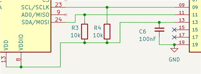
  • I would like to first set GPIO 13 to high (power source) and after that (with 10ms delay) enable GPIO pin 9 & 11 (numbers are from a connector ) and in my breadboard example P0.23 as powering GPIO and P0.26 + P0.27 as I2c Bus. 
    In the meantime i've tested to write it with the zephyr driver ( #include <drivers/i2c.h> ) without the Zephyr MPU9250 driver and I can read the sensor data while powering it from a GPIO. 

    This works (without driver - only hardcoded adresses) 

    	const struct device *gpio_dev1;
    	gpio_dev1 = device_get_binding(GPIO_DEV_NAME1);
    
    	if (!gpio_dev1) {
    		printk("Cannot find %s!\n", GPIO_DEV_NAME1);
    		//return;
    	}
    
    	ret = gpio_pin_configure(gpio_dev1, VDD_PIN1, GPIO_OUTPUT_ACTIVE);	
    	if (ret < 0) {
    		//return;
    	}
    
    	//nrfx_gpiote_out_set(VDD_PIN1);
    	gpio_pin_set(gpio_dev1, VDD_PIN1, 1);
    
    	printk(" Voltage on\n");
    	k_sleep(K_MSEC(MEASURE_INTERVAL*1000));
    
    	/******************************************************************
    	* i2c get binding
    	*/
    	const struct device *dev_i2c = device_get_binding("i2c0");
    	if (dev_i2c == NULL) {
    		printk("I2C Device not bounded\n");
    	}
    
    	/******************************************************************
    	* i2c read funktion
    	*/
    	//err = i2c_read(dev_i2c, &i2c_gelesen,2, 0x76);
    
    	err= i2c_burst_read(dev_i2c,0x68,0x43,sensorData,6);
    	if (err != 0) {
    			printk("Fehler beim Auslesen\n");
    	}
    
    	printk("Sensor Data: %u %u %u %u %u %u \n",sensorData[0],sensorData[1],sensorData[2],sensorData[3],sensorData[4],sensorData[5]);


    My goal is, to do this with the zephyr included mpu9250 driver. (Any communication with i2c should be done after setting the gpio power). 

    I think it could be erroring because i have the devices in the board overlay? maybe it does configure these at startup and cant find them because they aren't powered? 

    &i2c0 {
    
    	scl-pin = <25>;
    	sda-pin = <24>;
    	status = "okay";
    	/* 
    	mpu9250@68 {
    		compatible = "invensense,mpu9250";
    		gyro-sr-div = <0>;	//gyrscope sample rate divider
    		gyro-dlpf = <10>;	//digital low pass filter frequency
    		gyro-fs = <2000>;	//full scale of gyroscope. (Unit - DPS).
    		accel-fs = <8>;		//full scale of accelerometer
    		accel-dlpf = "10.2";
    		reg = <0x68>;
    		label = "MPU9250";
    		status = "ok";
    	
    	};

Reply

  • I would like to first set GPIO 13 to high (power source) and after that (with 10ms delay) enable GPIO pin 9 & 11 (numbers are from a connector ) and in my breadboard example P0.23 as powering GPIO and P0.26 + P0.27 as I2c Bus. 
    In the meantime i've tested to write it with the zephyr driver ( #include <drivers/i2c.h> ) without the Zephyr MPU9250 driver and I can read the sensor data while powering it from a GPIO. 

    This works (without driver - only hardcoded adresses) 

    	const struct device *gpio_dev1;
    	gpio_dev1 = device_get_binding(GPIO_DEV_NAME1);
    
    	if (!gpio_dev1) {
    		printk("Cannot find %s!\n", GPIO_DEV_NAME1);
    		//return;
    	}
    
    	ret = gpio_pin_configure(gpio_dev1, VDD_PIN1, GPIO_OUTPUT_ACTIVE);	
    	if (ret < 0) {
    		//return;
    	}
    
    	//nrfx_gpiote_out_set(VDD_PIN1);
    	gpio_pin_set(gpio_dev1, VDD_PIN1, 1);
    
    	printk(" Voltage on\n");
    	k_sleep(K_MSEC(MEASURE_INTERVAL*1000));
    
    	/******************************************************************
    	* i2c get binding
    	*/
    	const struct device *dev_i2c = device_get_binding("i2c0");
    	if (dev_i2c == NULL) {
    		printk("I2C Device not bounded\n");
    	}
    
    	/******************************************************************
    	* i2c read funktion
    	*/
    	//err = i2c_read(dev_i2c, &i2c_gelesen,2, 0x76);
    
    	err= i2c_burst_read(dev_i2c,0x68,0x43,sensorData,6);
    	if (err != 0) {
    			printk("Fehler beim Auslesen\n");
    	}
    
    	printk("Sensor Data: %u %u %u %u %u %u \n",sensorData[0],sensorData[1],sensorData[2],sensorData[3],sensorData[4],sensorData[5]);


    My goal is, to do this with the zephyr included mpu9250 driver. (Any communication with i2c should be done after setting the gpio power). 

    I think it could be erroring because i have the devices in the board overlay? maybe it does configure these at startup and cant find them because they aren't powered? 

    &i2c0 {
    
    	scl-pin = <25>;
    	sda-pin = <24>;
    	status = "okay";
    	/* 
    	mpu9250@68 {
    		compatible = "invensense,mpu9250";
    		gyro-sr-div = <0>;	//gyrscope sample rate divider
    		gyro-dlpf = <10>;	//digital low pass filter frequency
    		gyro-fs = <2000>;	//full scale of gyroscope. (Unit - DPS).
    		accel-fs = <8>;		//full scale of accelerometer
    		accel-dlpf = "10.2";
    		reg = <0x68>;
    		label = "MPU9250";
    		status = "ok";
    	
    	};

Children
Related