nPM1100 Charging IC - Reg

We have queries regarding nPM1100 charging IC, I have mentioned our queries below, Please share your response.

1. What is the main purpose for the shipping mode and purpose of SHPACT and SHPHLT pins ?
2. What is the main function for the Mode Pin ?
3. If we are charge our Li-ion battery, how can we know our battery is fully charged or not? Is there any provision for check the battery condition like fully charged or not ?
4. If we don't want to charge the battery ,how can we disable the charging though our MC?
5. What is the main purpose for the USB_D- and the USB_D+ pins.

Please share your clear update regarding the above queries.

Thanks,

Kodish.

Parents
  • Hi,

    Have you read the product specification for the PMIC? Most of your questions is answered there. 

    1. What is the main purpose for the shipping mode and purpose of SHPACT and SHPHLT pins ?

    Ship mode isolates the battery, reducing quiescent current.To enter Ship mode, SHPACT must be set high for a minimum period of tactiveToShip when VBUS is disconnected and SHPHLD held high (VIH). SHPACT has an internal pull-down resistor. SHIPACT can be connected to a microcontroller GPIO (using logic levels in the range VIL and VIH) or to a PCB test pin for activation at the end of production.

    2. What is the main function for the Mode Pin ?

    BUCK features two modes of operation: hysteretic and PWM. Hysteretic mode offers efficiency for the full range of supported load currents. PWM mode provides a clean supply operation due to a constant switching frequency, FBUCK. This provides optimal coexistence with RF circuits. BUCK can automatically change between Hysteretic and PWM modes. Modes are controlled by the MODE pin. The state of the MODE pin can be changed at any time.

    3. If we are charge our Li-ion battery, how can we know our battery is fully charged or not? Is there any provision for check the battery condition like fully charged or not ?

    The charging indication pin, CHG, is active while the battery is charging.

    4. If we don't want to charge the battery ,how can we disable the charging though our MC?

    You can try to use Ship mode?

    regards

    Jared 

  • Hi Jared,

    Thanks for the update.

    Please share your answer for 5th Question. What is the main purpose for the USB_D- and the USB_D+ pins ?

    How can we confirm, our battery is fully charged(100%) or not ?

    We have used Ship mode, In Ship mode, VSYS and VOUTB is LOW. So we can't Use Ship mode for our application. Please suggest some other modes.

    Thanks,

    Kodish.

  • Hi,

    Thanks for the support.

    1. We are not using the ship mode so we will connect this two pins to AVSS. If we need this function then we will connect to MCU's GPIO. Please confirm this.
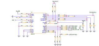
    2, Here I have attached the schematics. Please check and share your suggestion.

  • Hi,

    1. 2.2 µF decoupling capacitor is needed on VBUS.
    2. Decoupling capacitor on VSYS should be 22 µF
    3. Can you explain why have connected VOUTBSET0 and VOUTBSET1 and DEC that way?

    The rest looks ok.

    Kodish said:
    . We are not using the ship mode so we will connect this two pins to AVSS. If we need this function then we will connect to MCU's GPIO. Please confirm this.

    Using ship mode is optionally. So this should be ok. 

    regards

    Jared

  • Hi,

    Thanks for the update, 

    2.2 µF decoupling capacitor is needed on VBUS
    Decoupling capacitor on VSYS should be 22 µF

    OK. We will change the Value.

    1. Can you explain why have connected VOUTBSET0 and VOUTBSET1 and DEC that way?


    For DEC we have connected the 10uF cap as per your ref schematics. For  VOUTBSET0 and VOUTBSET1, we need both 3V and 1.8V sonly we have connect like this. R561 and R560 both components are DNP.

    Please check this and share your suggestions.

    Thanks,

    Kodis.

  • Hi,

    I see, just remember that the VOUTBSET0 and VOUTBESET1 should be maximum VINT + 0V3, which means that the maximum voltage that you should expose those pins are dependent on what the SYSREG is configured too.

    regards

    Jared 

  • Hi Jared,

    In our existing PMIC , we have a pin  that changes its state when USB is connected .So we have connected that to interrupt pin of MCU and with this we can know the status immediately incase of power loss  .Whether same such feature /Pin is available in nPM1100 .Please let us know.

    Thanks,
    Kodish

Reply Children
Related