This discussion has been locked.
You can no longer post new replies to this discussion. If you have a question you can start a new discussion

nPM1100 voltage

We observe something that I can’t explain at the moment. Could you help to find the root of the issue, please? See below.

 1. When the battery is connected first, and the Charge In (USB) after – we observe SYS 3.7V when running on battery, 5.0V when USB is plugged in, back to 3.7V when USB is unplugged. Everything seems to be normal.

2  When the USB is connected first, and the battery is connected after – we observe SYS 5.0V when running on USB only, 5.0 when the battery is plugged in, 7.4V after ~ 0.5 sec after the USB is unplugged. Looks like the battery voltage is doubled. When the USB is plugged back – it is still 7.4V. Only after the battery is unplugged – it drops back to 5.0V.

 3. We tried to cover the PMIC with black insulation tape (to protect from light) – it doesn’t make any difference.


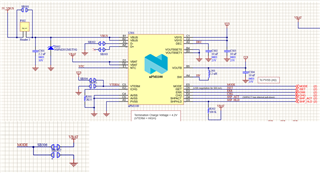
Loads on SYS line – nRF5340 and Maxim AFE chip

Parents
  • Hi Wes

    This is very strange! There's no charge pump anywhere in the system, so I can't see how the voltage can be this high. Can you ask them to  measure VBAT / VBUS / VOUTB level pin when they observe 7.4V on VSYS?

    When the battery is disconnected, you have to cycle VBUS in order to charge the battery. But VSYS should follow what's highest of VBUS or VBAT. 

    cheers,

    Ketil

  • Only VBUS is connected:

    VBUS = 5.0V

    VBAT = 0

    VSYS = 5.0 V

    VOUTB = 1.8 V


    VBUS is connected and battery (4.0V) is plugged:

    VBUS = 5.0V

    VBAT = 4.0

    VSYS = 7.7 V

    VOUTB = 2.0 V

    one more question also:

    No FW loaded into nRF5340.


    1. When no battery connected and VDDH is applied (in the range 4.0 – 5.0 V) then VDD = 1.8 V.
    2. When battery is connected (on PMIC VBUS = 5.0V, VSYS = 4.2V and VDDH = VSYS = 4.2 V, on nRF53 module VBUS pin is not powered or powered with 5.0 V – same effect) then VDD = 3.3 V. Why?
    3. Is my understanding correct: if VREGH.DCDCEN, VERGMAIN.DCDCEN, VERGRADIO.DCDCEN are set to “DCDC” and UICR.VERGHVOUT is set to 1.8V – then GPIO, System Power Application Core and Radio Power Network Core all will be set to 1.8V?
  • IT turns out that the MODE pin was connected to VBAT and also to P1.00 of the NRF5340.

    Apparently, connecting the battery when the entire system is already powered from VBUS caused both issues:

     High (7V ) voltage issue.

    Changing level of VDD from 1.8V to 3.3V

    would you have any thoughts on why applying VBAT to P1.00 (and MODE pin on PMIC) might caused these issues?

Reply
  • IT turns out that the MODE pin was connected to VBAT and also to P1.00 of the NRF5340.

    Apparently, connecting the battery when the entire system is already powered from VBUS caused both issues:

     High (7V ) voltage issue.

    Changing level of VDD from 1.8V to 3.3V

    would you have any thoughts on why applying VBAT to P1.00 (and MODE pin on PMIC) might caused these issues?

Children
  • Hi Wes

    If VBAT is connected to a GPIO, it's violating the spec if VBAT is higher than VDD + 0.3 V. In this case, the ESD protection diode will start to conduct and lift VDD, this should no happen.

    So it can be something there that causes this. But VSYS at 7.7 V, no way! If nPM1100 VBUS=5.0V, VSYS can't be 4.2V.

    Do you have the full schematic for this?

    cheers,

    Ketil

Related