Beware that this post is related to an SDK in maintenance mode
More Info: Consider nRF Connect SDK for new designs

How to generate multiple signals with timing controls (nRF52840)

Hi Nordic community

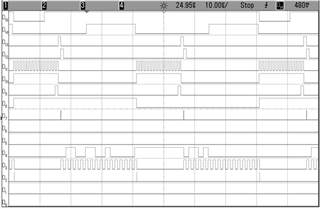
We have a custom IC to interface with the nRF52840 chip. We did testing for that IC with FPGA and the related control, clock signals are as shown in the figure below. The frequency of these signals when interfacing with nRF52840 will be slower, with the highest frequency of 1 MHz. 

It's not too hard to generate these signals with precise timing controls in FPGA but I'm wondering if this is doable with nRF52840? And would you recommend a good strategy to do it (nRF5 SDK or nRF Connect SDK are both fine for us)?
Thanks,

Richard

  • xxb9075 said:
    Would you explain the interrupt latency table a little bit more?

    These were only the interrupt latency delays, it does not include the time the softdevice may be executing code in a higher level interrupt, e.g. this is shown here:
    https://infocenter.nordicsemi.com/topic/sds_s140/SDS/s1xx/ble_processor_avail_interrupt_latency/ble_peripheral_connection_performance.html

    So you can't just run the code at any time, you need to schedule this between BLE events.

    xxb9075 said:
    And then for the strategy to generate these signals, OUTSET and OUTCLR are better than OUT because they will only alter pins that are specified?

    Yes.

    xxb9075 said:
    Would I be able to perform an XOR of OUT and 0xFFFFFFFF (the pins that need to be toggled are set to 1) to achieve the same goal?

    No.

    xxb9075 said:
    To generate the timing, what do you recommend if we can slow things down? Shall we use a timer to generate such interrupts and toggle OUT/OUTSET/OUTCLR in the ISR?

    I don't know, I think it can become very slow if you need to base this on a timer interrupt.

    hmolesworth said:
    Some of the signals look synchronous so it may be possible to use multiple PWMs each of which has up to 4 pins; waveform mode (3 pins per PWM) can be used to encode sequences without interrupts

    A good point that PWM can be used, my worry though is the input pin that I assume might need to read during this sequence also, and that starting and stopping PWM (e.g. to updated the sequence) can also take a a few us.

    Kenneth

  • Thanks Kenneth,

    That's very helpful. To follow up:

    May I know the reason why we cannot perform XOR to OUT register?

    Would the implementation with nRF Connect SDK based on Zephyr be any different from the nRF5 SDK Softdevice approach? Based on your experience, what would be a safe application interrupt frequency if we use the softdevice.

    For PWM, If we use all 4 PWM instances then we can control 12 pins in waveform modes? Assume that's enough for us, if there a way to sync the waveforms between different PWM instances?

    Thanks,

    Richard

  • xxb9075 said:
    May I know the reason why we cannot perform XOR to OUT register?

    I might misunderstood what you wanted to do here, it's a normal register that control output level for all the pins on the entire port, so you can do whatever operation you like, but you will always control all the pins on the port every time you write to the register.

    xxb9075 said:
    For PWM, If we use all 4 PWM instances then we can control 12 pins in waveform modes? Assume that's enough for us, if there a way to sync the waveforms between different PWM instances?

    Since you need 4PWM instances, the PPI will require 4 clock pulses (@64MHz) to start them all (e.g. from a timer compare event), however, since the GPIO peripheral is running internally on a 16MHz clock that run ascync to the 64MHz clock, I assume some of the 4 PWM peripherals will be off by a 16MHz period. 

    Best regards,
    Kenneth

  • PWM 16MHz clock is synchronous to 64MHz clock since 16MHz is derived from the 64MHz with a /4 circuit. Timer can generate 4 simultaneous starts for all 4 PWM peripherals (12 channels) via PPI using a single timer using either 2 timer compare registers with a Fork for each or 4 timer compare registers without Forks; the compare registers (2 or 4) should all be set to the same value so the PWM channels start their waveforms synchronously. For best accuracy keep the HFCLK crystal running and use a timer not an RTC for synchronous start.

    I should add that you might be able to use normal mode instead of waveform mode for 1 or more PWMs if the associated pins only need to generate a continuous fixed clock signal which would give 4 output pins for those non-waveform PWMs. More info on sequence is required to comment further.

Related