False IQ signal

Hi,

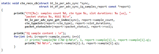
i have two nRF52833 program for make AOA. One is programe as Tx with "direction_finding_connectionless_tx" and one is program as receiver with "direction_finding_connectionless_rx" that i have modified to print IQ data link with an antenna array (of 4 antenna) : 

All compile well and the antenna swicthing works well too but i have a problem with IQ signal.

When i put my tx on the left of the antenna array (side of ant 1) i trace the IQ data that i receive and it's not coherent:

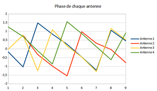
Indeed, the IQ signal of the ant4 and 3 is in advance compare to the IQ signal of ant1 an i don't understand why

Do you have an idea ?

Please i really need help so if you can help me i'm more than interested :)

Parents Reply Children
  • Hello Theo, sorry about the delay

    Are there any updates from your side?

    First of all, note that it is hard to judge the I/Q data by itself. It is recommended to look at the vectors or the resulting angles instead.

    So your antenna array has 4 antennas? What pattern, sample spacing and sample duration are you using? Keep in mind that the antenna pattern used in the sampling period depends on the sampling in the reference period, getting you a different switch pattern (for more info see our whitepaper on DF). Are you sure that you are looking the right antennas in your graph?

    Another thing is that the samples aren't taken at the same instant. Radio peripheral takes samples one after another for antennas configured by antenna switching pattern. To evaluate angles according to method described in whitepaper nWP036 you have to apply correction to received IQ samples. You have to correct phase by angle related with the delay between first and particular sample. 

    Regards,

    Elfving

Related