This post is older than 2 years and might not be relevant anymore
More Info: Consider searching for newer posts
This discussion has been locked.
You can no longer post new replies to this discussion. If you have a question you can start a new discussion

power on reset time

Hi Team, about power on reset time, not very clear about the description in the SP3.1 as in the attached picture, image description 
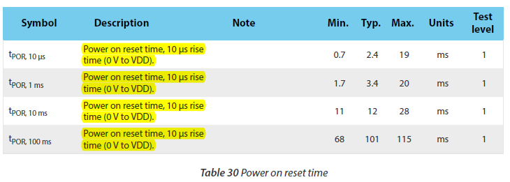
why the description are the same? what's the difference between tPOR,10us / tPOR,1ms /tPOR,10ms /tPOR,100ms

thanks, vincent

  • Hi. This is a documentation error. I it should say 10us, 1ms, 10ms and 100ms in the descriptions as well. It is reported to our technical writers. Thank you for bringing it to our attention.

    EDIT:

    The reason why t_POR is longer than the rise time, e.g. with 10us rise time t_POR is 2.4ms, is that the nRF51's internal voltage regulators need some time to stabilize before the CPU is allowed to read from flash.

  • Hi, thanks,

    1. does it mean the POR time is typical 2.4ms if the rise time from 0v to VDD is 10us? POR time is the time from 0v to the time when nrf51822 comeout of reset state and nrf51822 start to run(should be 1.8v), so, the POR time should be not bigger than the rise time from 0v to VDD, is that right?
    2. if it's right, how to explain the parameters in the table(POR time is bigger than the rise time)?
    3. if the rise time from 0v to vdd(3v) is about 300us, how about the power on reset time? which reference parameter should we take? tPOR,10us or tPOR,1ms?

    thanks, vincent

  • With a 300us rise time I can't give you any exact values. I would suggest that you use an estimated value. Maybe something in between the values for 10us and 1ms rise time values, like 2.7ms.

Related