Hello Nordic,
I am using nRF 52840 (SPI Master) with RHD2216(SPI Slave) to get sample data through SPI.
I have used the nRF connect SDK v1.9.0 SPI example to build my application as a reference.
This application is working fine, but when the timer period is set to 1 MSEC, the main loop will be blocked, and the main problem I think is the low operating speed of the spi_transieve function.
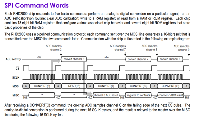
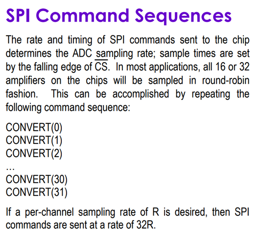
As a reference, when using spi_transieve API to send a data array in one spi_transieve calling, the speed is same as the spi_config setting. However, using the round-robin fashion to send the same size data with many spi_transieve calling, the speed is going to slow down, and the gap is huge, like ten times.
But using the round-robin fashion is the recommended way by Intan to configure the RHD2216 chip.
Please let me know if this spi_transieve API can be faster in the round-robin fashion to meet the Intan chips' demand.
I have attached my code along with a link of the data sheet for Intan RHD2216.
/*
 * Copyright (c) 2012-2014 Wind River Systems, Inc.
 *
 * SPDX-License-Identifier: Apache-2.0
 */
/*
 * include
 */
#include <zephyr.h>
#include <sys/printk.h>
#include <drivers/spi.h>
#include <drivers/gpio.h>
#include <device.h>
#include <devicetree.h>
#include <kernel.h>

typedef unsigned char u8_t;
typedef unsigned short u16_t;
/*
 * marco define and struct define
 */
// marco define
#define SLEEP_TIME_MS   2000
#define BLE_BUFFER_SIZE  190 // 10 sample 1 BLE packet
static u16_t T_result[19];
// RHD command
// CONVERT command  LSB set to 0(option)TODO
static u16_t RHD_CONVERT[19] = {0x0000 ,0x0100 ,0x0200 ,0x0300 ,0x0400 ,0x0500 ,0x0600 ,0x0700 ,
										0x0800 ,0x0900 ,0x0a00 ,0x0b00 ,0x0c00 ,0x0d00 ,0x0e00 ,0x0f00 ,0xFF00 ,0xFF00 ,0xFF00};
										// 16 channels + 3 dummy command(read ROM 63)(user define)
										// 0x3f00 -> CONVERT(63)
// ADC self-calibration command ,this command needs nine dummy command to generate the necessary clock cycles to run.
#define CALIBRATE  0x5500
static const u16_t NINE_DUMMPY[9] = {0xbf00 ,0xbf00 ,0xbf00 ,0xbf00 ,0xbf00 ,0xbf00 ,0xbf00 ,0xbf00 ,0xbf00};
#define CLEAR   0x6A00 // not necessary to use this command
 // Registers configuration using write command
#define Register0    0x80DE// amp fast settle is 0 ,20-150HZ filter ,enable ADC AND amp(disable is OK)
#define Register1    0x8120 // VDD sense disable ,using 16 * 1KS/s ADC
#define Register2    0x8228 // MUX bias current, configuration as above
#define Register3    0x8302 //diable tempS and digout
#define Register4    0x84B0 // absmode enable + unsigned ADC + weak MISO + DSP high-pass filter enable(differentiator)
// Impedance check
#define Register5    0x8500 // Impedance check control ,which is disable
#define Register6    0x8600 // DAC output voltage ,there is 0
#define Register7    0x8700 // Impedance check electrode select, this is 0
// on-chip Amplifier bandwidth Select
#define Register8    0x882C //  using 20-150 Hz bandwidth
#define Register9    0x8911
#define Register10    0x8a08
#define Register11    0x8b15
#define Register12    0x8c36
#define Register13    0x8d00
// indicidual Amplifier Power ,all set to one for using all channels' Amplifier
#define Register14    0x8eff
#define Register15    0x8fff
#define Register16    0x90ff
#define Register17    0x91ff

// BLE buffer database
// there is a test BLE buffer
static u16_t BLE_buffer[BLE_BUFFER_SIZE];
static int BLE_buffer_inds = 0;
// spi struct
static u16_t tx_buffer[1];
static u16_t rx_buffer[1];
	const struct spi_buf tx_buf = {
		.buf = tx_buffer,
		.len = sizeof(tx_buffer)
	};
	const struct spi_buf_set tx = {
		.buffers = &tx_buf,
		.count = 1
	};

	struct spi_buf rx_buf = {
		.buf = rx_buffer,
		.len = sizeof(rx_buffer),
	};
	const struct spi_buf_set rx = {
		.buffers = &rx_buf,
		.count = 1
	};
// LED
/* The devicetree node identifier for the "led0" alias. */
#define LED0_NODE DT_ALIAS(led0) // macro function of devicetree

#if DT_NODE_HAS_STATUS(LED0_NODE, okay)
#define LED0	DT_GPIO_LABEL(LED0_NODE, gpios)
#define PIN	DT_GPIO_PIN(LED0_NODE, gpios)
#define FLAGS	DT_GPIO_FLAGS(LED0_NODE, gpios)
#else
/* A build error here means your board isn't set up to blink an LED. */
//#error "Unsupported board: led0 devicetree alias is not defined"
#define LED0	""
#define PIN	 0
#define FLAGS	0
#endif
// SPI RHD cs
#if DT_SPI_HAS_CS_GPIOS(DT_NODELABEL(spi1))
#define RHD2216    DT_SPI_DEV_CS_GPIOS_LABEL(DT_NODELABEL(a)) // get CS label a is RHD2216
#define RHD_PIN    DT_SPI_DEV_CS_GPIOS_PIN(DT_NODELABEL(a)) // get RHD cs pin
#define RHD_FLAGS  DT_SPI_DEV_CS_GPIOS_FLAGS(DT_NODELABEL(a)) // get RHD FLAGS
#else
#define RHD2216   ""
#define RHD_PIN   0
#define RHD_FLAGS   0
#endif

// timer
struct k_timer RHD_timer;
extern void my_timer_handler(struct k_timer *timer_id); // cb function call

// SPI
struct device * spi_dev;
static struct spi_cs_control spi_cs;
struct device * RHD_dev; // Define a pointer to the device structure
// spi config


static const struct spi_config spi_cfg = {
	.operation = SPI_WORD_SET(8) | SPI_TRANSFER_MSB |
		     SPI_MODE_CPOL | SPI_MODE_CPHA ,
	.frequency = 16000000 ,
//	.slave = 0,
};

// RHD_CS
// const struct device *RHD_dev; // Define a pointer to the device structure
bool RHD_SAMPLE = true;
int ret;
int RHD_err;
// LED Blinky
const struct  device *LED_dev;
bool led_is_on = true;
int ret_LED;
static struct k_poll_signal cs_signal;

/*
 * function define
 */
// timer function

// SPI
static void spi_init(void)
{
	const char* const spiName = "SPI_1"; //SPI1 label
	spi_dev = device_get_binding(spiName);
cs_signal.signaled = 0;

	if (spi_dev == NULL) {
		printk("Could not get %s device\n", spiName);
		return;
	}
}

u16_t spi_trans(u16_t command) // SPI trans in the timer period
{
	int err;
	tx_buffer[0] = command;
	err = spi_transceive(spi_dev, &spi_cfg, &tx, &rx);
	RHD_SAMPLE = !RHD_SAMPLE;
	if (err) {
		printk("SPI error: %d\n", err);
		return -1;
	} else {
		return rx_buffer[0];
	}
}
// RHD init function
static int RHD2216_init(void){
	static const u16_t Register_config[18] = {Register0 ,Register1 ,Register2 ,Register3 ,Register4 ,Register5 ,Register6 ,Register7 ,
										  Register8 ,Register9 ,Register10 ,Register11 ,Register12 ,Register13 ,Register14 ,Register15 ,
										  Register16 ,Register17};
	static u16_t result[18];
	int err;
	u16_t calibrate_err;
	for(int i=0 ;i <sizeof(Register_config) / 2;i++){
		result[i] = spi_trans(Register_config[i]);
	}
	k_sleep(K_USEC(100)); // 100us delay before ADC calibrate
	calibrate_err = spi_trans(CALIBRATE);
	for(int j=0 ;j<9;j++){ // using generate nine SCLK to calibrate ADC
		calibrate_err = spi_trans(NINE_DUMMPY[j]);
	}
	if(calibrate_err == 0xbf00){ // only check last calibrate result this is a loopback test ,true value is 0x8000 TODO
		printk("calibrate success! \n");
	}else{
		err = 1;
		return err;
	}
	// loopback test ,to test the correct result (write command result) TODO
	for(int j=0 ;j <sizeof(Register_config) / 2;j++){
		if(result[j] == Register_config[j]){
			err = 0;
		}else{
			err = 1;
			return err;
		}
	}
	return err;

}
/*
 * cb function define
 */
// timer cb
void RHD_handler(struct k_work *work) // using round-robin fashion ,a timer callback to sample all needed channels
{
	// static u16_t T_result[19];
	uint64_t stamp;
	int64_t delta;
	stamp = k_uptime_get_32();
    /* do the processing that needs to be done periodically */
	for(int j = 0;j<10;j++){
	for(int i = 0; i<19;i++){
	T_result[i] = spi_trans(RHD_CONVERT[i]);
	}}
	delta = k_uptime_delta(&stamp);
	printk("SPI Use time is:%lld ms \n", delta);

}
K_WORK_DEFINE(my_work, RHD_handler); // define RHD_handler as my_work
void my_timer_handler(struct k_timer *dummy)
{
    k_work_submit(&my_work);
}
/*
 * main function loop
 */
void main(void)
{
	/*
	 * setup
	*/
	// timer
	k_timer_init(&RHD_timer, my_timer_handler, NULL); // init timer
	// blinky LED setup
	// Extract the device driver implementation
	LED_dev = device_get_binding(LED0); // combine the driver and devicetree node
	if (LED_dev == NULL) {
		return;
	}
	// Configure the GPIO pin
	ret_LED = gpio_pin_configure(LED_dev, PIN, GPIO_OUTPUT_ACTIVE | FLAGS);
	if (ret_LED < 0) {
		return;
	}
	// SPI
	printk("SPIM Example\n");
	spi_init();
	printk( "RHD_FLAGS %x\n",RHD_FLAGS);
	RHD_err = RHD2216_init();
	if(RHD_err){
		printk("RHD2216 init fail \n");
	}else{
		RHD_err = spi_trans(RHD_CONVERT[0]);
	/* start periodic timer that expires once at 1kHz */
	k_timer_start(&RHD_timer, K_SECONDS(3), K_USEC(5000)); // first param is timer duration(initial timer duration)
	}
	/*
	 * Loop function : other data process code
	*/
	while(true){
		printk("This is main loop! \n");
		if(BLE_buffer_inds == BLE_BUFFER_SIZE){
			// start BLE trans TODO
			printk("BLE trans start! \n");
			BLE_buffer_inds = 0;
		}
	}

}
http://intantech.com/files/Intan_RHD2000_series_datasheet.pdf


