Clarification on how to generate a 10kHz sine wave with PWM and DMA

I'm struggling when using PWM and DMA to generate a sine wave. I'm sure I'm not interpreting the documentation right, and I hope someone can point me in the right direction

I tried the following code

#include <stdio.h>
#include <string.h>
#include "nrf_drv_pwm.h"
#include "app_util_platform.h"
#include "app_error.h"
#include "boards.h"
#include "bsp.h"
#include "app_timer.h"
#include "nrf_drv_clock.h"

#include "nrf_log.h"
#include "nrf_log_ctrl.h"
#include "nrf_log_default_backends.h"

static nrf_drv_pwm_t m_pwm = NRF_DRV_PWM_INSTANCE(0);

static void init_bsp()
{
    APP_ERROR_CHECK(nrf_drv_clock_init());
    nrf_drv_clock_lfclk_request(NULL);

    APP_ERROR_CHECK(app_timer_init());

}


void app_error_fault_handler(uint32_t id, uint32_t pc, uint32_t info)
{
    bsp_board_leds_on();
    app_error_save_and_stop(id, pc, info);
}

static void demo(void)
{
    NRF_LOG_INFO("Demo 1");

    /*
     * 
     */
    // This array cannot be allocated on stack (hence "static") and it must
    // be in RAM (hence no "const", though its content is not changed).
    static nrf_pwm_values_wave_form_t /*const*/ m_demo_seq_values[] =
    {
        500,500,500,1000,
        578,578,578,1000,
        655,655,655,1000,
        727,727,727,1000,
        794,794,794,1000,
        854,854,854,1000,
        905,905,905,1000,
        946,946,946,1000,
        976,976,976,1000,
        994,994,994,1000,
        1000,1000,1000,1000,
        994,994,994,1000,
        976,976,976,1000,
        946,946,946,1000,
        905,905,905,1000,
        854,854,854,1000,
        794,794,794,1000,
        727,727,727,1000,
        655,655,655,1000,
        578,578,578,1000,
        500,500,500,1000,
        422,422,422,1000,
        345,345,345,1000,
        273,273,273,1000,
        206,206,206,1000,
        146,146,146,1000,
        95,95,95,1000,
        54,54,54,1000,
        24,24,24,1000,
        6,6,6,1000,
        0,0,0,1000,
        6,6,6,1000,
        24,24,24,1000,
        54,54,54,1000,
        95,95,95,1000,
        146,146,146,1000,
        206,206,206,1000,
        273,273,273,1000,
        345,345,345,1000,
        422,422,422,1000
    };

    static nrf_pwm_sequence_t const    m_demo_seq =
    {
        .values.p_wave_form  = &m_demo_seq_values,
        .length              = NRF_PWM_VALUES_LENGTH(m_demo_seq_values),
        .repeats             = 0,
        .end_delay           = 0
    };

    nrf_drv_pwm_config_t const config =
    {
        .output_pins =
        {
            ARDUINO_A0_PIN,
            NRFX_PWM_PIN_NOT_USED,
            NRFX_PWM_PIN_NOT_USED,
            NRFX_PWM_PIN_NOT_USED
        },
        .irq_priority = APP_IRQ_PRIORITY_LOWEST,
        .base_clock   = NRF_PWM_CLK_16MHz,
        .count_mode   = NRF_PWM_MODE_UP,
        .top_value    = 40,
        .load_mode    = NRF_PWM_LOAD_WAVE_FORM,
        .step_mode    = NRF_PWM_STEP_AUTO
    };
    APP_ERROR_CHECK(nrf_drv_pwm_init(&m_pwm, &config, NULL));

    (void)nrf_drv_pwm_simple_playback(&m_pwm, &m_demo_seq, 1,
                                      NRF_DRV_PWM_FLAG_LOOP);
}


int main(void)
{
    APP_ERROR_CHECK(NRF_LOG_INIT(NULL));
    NRF_LOG_DEFAULT_BACKENDS_INIT();

    init_bsp();

    NRF_LOG_INFO("PWM example started.");

    demo();

    for (;;)
    {
        // Wait for an event.
        __WFE();

        // Clear the event register.
        __SEV();
        __WFE();

        NRF_LOG_FLUSH();
    }
}

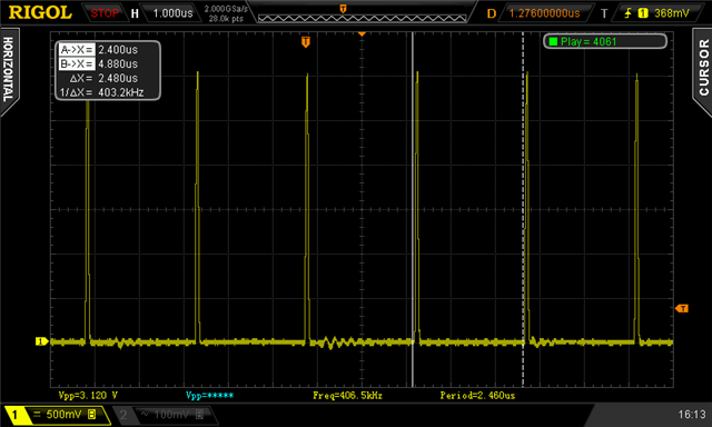
If I understand correctly how PWM works, with a 16MHz clock and a 1000 counter top, should give me a "pwm step" of 16kHz. Since I have 40 elements in the sine lookup table, the resulting sine frequency should be 400Hz. And I get something very close (minus the analog filtering part, that I'm still trying to figure out how to do properly)

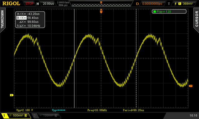
In order to get to 10kHz, I need to reduce counter top to 40, and use 40 steps for the sine lookup table (or any similar combination, 40 and 40 just happens to work nicely with a 16Mz clock). Which seems rather low to get a good sine wave. I tried using the following, and sure enough I get a 10kHz wave

    static nrf_pwm_values_wave_form_t /*const*/ m_demo_seq_values[] =
    {
	    20,0,0,40,
        23,0,0,40,
        26,0,0,40,
        29,0,0,40,
        32,0,0,40,
        34,0,0,40,
        36,0,0,40,
        38,0,0,40,
        39,0,0,40,
        40,0,0,40,
        40,0,0,40,
        40,0,0,40,
        39,0,0,40,
        38,0,0,40,
        36,0,0,40,
        34,0,0,40,
        32,0,0,40,
        29,0,0,40,
        26,0,0,40,
        23,0,0,40,
        20,0,0,40,
        17,0,0,40,
        14,0,0,40,
        11,0,0,40,
        8,0,0,40,
        6,0,0,40,
        4,0,0,40,
        2,0,0,40,
        1,0,0,40,
        0,0,0,40,
        0,0,0,40,
        0,0,0,40,
        1,0,0,40,
        2,0,0,40,
        4,0,0,40,
        6,0,0,40,
        8,0,0,40,
        11,0,0,40,
        14,0,0,40,
        17,0,0,40
    };

Do I understand correctly the relationship between counter top and the values in the sequence array? Is there a way to do better than what I'm doing in generating a 10kHz sine wave? An old trick for memory limited processors was to store only the first 90 degrees of the sine table, and "mirror" it 4 times, as appropriate, but I could not think of a way to make it work here

Since I need only one channel, do I need to have the nrf_pwm_values_wave_form_t array to have all those 0 values, or is there a way to save memory? 

Lastly, any idea why I get a "warning: initialization of 'const nrf_pwm_values_wave_form_t *' from incompatible pointer type 'nrf_pwm_values_wave_form_t (*)[20]' [-Wincompatible-pointer-types]" in line 88? I thought I used the pointers as defined by nrf_pwm.h

Parents
  • Since in PWM mode here COUNTERTOP is a fixed number, there is no need for waveform mode, instead use Common mode and a single pin connected. That requires a single 16-bit number for each step (instead of 4 numbers per step in waveform mode). Up/Down might give a better sine curve (instead of Up, but it doesn't matter other than maybe halving the memory requirement).

    The CR filter is just that, a resistor feeding a capacitor to Gnd with the output at the CR junction. -3dB frequency set to (say) 10kHz gives 50% of available signal at the CR junction output. f=1/2pieCR, but very high values of R will be a problem depending on the impedance of the connected circuit being driven. Avoid polarised Tants, instead use ceramics for the capacitor. Maybe try 150R 100nF for 10kHz -3dB. Need to set PWM output pin to H0H1 drive levels, by the way, since driving a capacitive load

    PDM mode might be a better option if there is too much distortion when you test this PWM; note PDM mode would require using PWM Waveform with a corresponding larger (more complex) table.

    Why only 40 steps, by the way? More steps and a faster net clock would give a better (cleaner) output unless you are very short of memory. 1600 steps (3200 bytes) is an option is it not ..

    Edit: I should add that the CR introduces a phase shift so the known zero-crossing position isn't; This can be allowed for, preferably with a ratiometric measurement using a fixed phase shift via (say) a calibrated CR network. The frequency step must be "smooth" between end-of-table and start-of-table to avoid a discontinuity in the measurement (in audio terms an annoying "click"). This is best handled by choosing  a frequency very close to 10kHz which has an integral number of steps where the exact 10kHz sample might not otherwise be integral. Another reason for lots of steps

  • Why only 40 steps, by the way? More steps and a faster net clock would give a better (cleaner) output unless you are very short of memory. 1600 steps (3200 bytes) is an option is it not ..

    Thanks for your answer, but either I misunderstand you or my understanding of the way a PWM works is wrong... or both Slight smile

    We start from a 16MHz clock. The first decision is how many steps of that 16MHz clock our PWM period uses. That is what Nordic calls counter top, and defines the resolution of the PWM. I landed on 40, to strike the best possible balance between sine points and resolution. So each PWM period has 40 steps, and each step is 2.5% duty cycle.

    That results in a PWM frequency of 400kHz (16MHz/40). In order to generate a 10kHz sine, I can only use 40 points to define a single sine. I could use more points for the sine, but I would have fewer steps for the resolution. I chose 40 and 40 as a compromise between the competing requirements of the vertical and horizontal resolution. If the main clock were higher (some processors can use up to 256MHz clocks), I could increase both

    What am I doing wrong?

    I will try your Common-vs-waveform mode comment, I think I understand what you mean. But it would not change the resolution/frequency, which is the main concern now. I'm not sure that a 40 point.40 values sine would be anywhere near good enough to measure a phase shift from what I see on my scope, but maybe I can use a better output filter. I'm also not sure if the pin I used is properly configured, need to check

  • The PWM choices are dictated by the prescaler used, divide 16MHz by 1 , 2, 4, 8 etc;, This might be clearer:

    // PWM frequency input with prescale /1: 16MHz
    //
    // COUNTERTOP   Steps  Resolution in % Output Frequency          Memory (bytes)
    // ==========   =====  =============== ========================= ==============
    //    1600       1600  1/1600 = .0625  16,000,000/1,600 =  10kHz 1600*2=3200
    //      40         40  1/  40 = 2.5    16,000,000/   40 = 400kHz   40*2=  80
    
    
    // PWM frequency input with prescale /8:  2MHz
    //
    // COUNTERTOP   Steps  Resolution in % Output Frequency          Memory (bytes)
    // ==========   =====  =============== ========================= ==============
    //     200        200  1/ 200 = 0.5     2,000,000/  200 =  10kHz  200*2= 400
    //      40         40  1/  40 = 2.5     2,000,000/   40 =  50kHz   40*2=  80

  • Yes, thanks. I understand how the prescalers relate to the clock and PWM frequency.

    Let's use 16MHz clock and 40 COUNTERTOP, as in your example. That means that each single PWM pulse is at 16MHz, and I need 40 of those to represent every possible number from 0 to 40. So I have only 400kHz "values" with which to form a sine wave. Let's call COUNTERTOP the vertical resolution of the XY sine graph. So I have 40 Y values to play with.

    Now I need enough X values to represent a sine. Given that I need a 10kHz sine wave, I can use 40 X values to represent one period of my sine. So now my frequency is 400kHZ/40=10kHZ. My sine has a resolution, so to speak, of 40x40 pixels.

    If I were to use, say, 80 values for X, the frequency of my sine would be only 5kHz, 400kHz/80.

    In the following oscilloscope screenshot, I'm using prescaler 1, 16MHz clock, 40 COUNTERTOP and sending the value 1, a single pulse. The overall frequency is 400kHz (my scope is picking up a slightly different one, I think it's noise, I just hacked things together badly)

    So far, so good: each pulse is at 16MHz, and I need 40 to represent a PWM value ("cycle")

    Now I use a table with 40 values, forming a LUT for a sine (the one in my code above), and I see, as expected, a 10kHz sine wave. Badly filtered because I only had around the wrong RC values, but the overall frequency won't change, just how clean the sine looks 

    So now I ask again: what am I missing? How can I use more entries in the LUT without either reducing too much the vertical resolution or changing frequency? 40 and 40 is all I can do to make things work, and I don't understand how to program the nRF52840 any different. I could do 20 and 80, but it would be a worse compromise

    If I needed a 1kHz sine wave, then, yes, I could use higher countertop and more table entries... 

Reply
  • Yes, thanks. I understand how the prescalers relate to the clock and PWM frequency.

    Let's use 16MHz clock and 40 COUNTERTOP, as in your example. That means that each single PWM pulse is at 16MHz, and I need 40 of those to represent every possible number from 0 to 40. So I have only 400kHz "values" with which to form a sine wave. Let's call COUNTERTOP the vertical resolution of the XY sine graph. So I have 40 Y values to play with.

    Now I need enough X values to represent a sine. Given that I need a 10kHz sine wave, I can use 40 X values to represent one period of my sine. So now my frequency is 400kHZ/40=10kHZ. My sine has a resolution, so to speak, of 40x40 pixels.

    If I were to use, say, 80 values for X, the frequency of my sine would be only 5kHz, 400kHz/80.

    In the following oscilloscope screenshot, I'm using prescaler 1, 16MHz clock, 40 COUNTERTOP and sending the value 1, a single pulse. The overall frequency is 400kHz (my scope is picking up a slightly different one, I think it's noise, I just hacked things together badly)

    So far, so good: each pulse is at 16MHz, and I need 40 to represent a PWM value ("cycle")

    Now I use a table with 40 values, forming a LUT for a sine (the one in my code above), and I see, as expected, a 10kHz sine wave. Badly filtered because I only had around the wrong RC values, but the overall frequency won't change, just how clean the sine looks 

    So now I ask again: what am I missing? How can I use more entries in the LUT without either reducing too much the vertical resolution or changing frequency? 40 and 40 is all I can do to make things work, and I don't understand how to program the nRF52840 any different. I could do 20 and 80, but it would be a worse compromise

    If I needed a 1kHz sine wave, then, yes, I could use higher countertop and more table entries... 

Children
No Data
Related