nRF51822 current consumption during BLE advertising

Hello, guys.

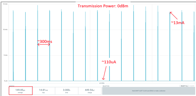
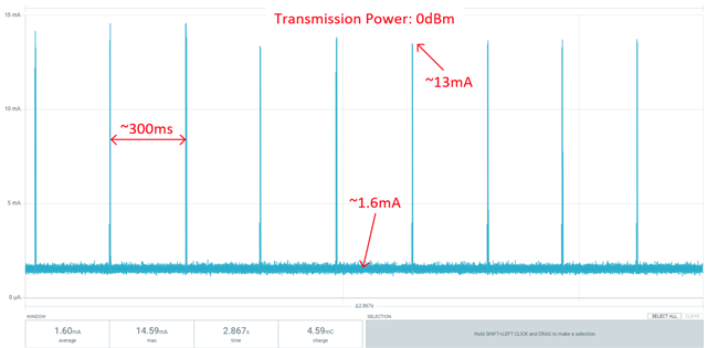
We are using nRF51822 SoC in our project. I would really appreciate your help with the expected current consumption in BLE advertising mode. Here is what we record with the Power Profile Kit II (BLE advertising interval is set to ~300ms and transmission power is equal to 0dBm):

We are using the Power Management library that is supposed to put the CPU in System ON sleep mode between two advertising cycles because we don't have any other activity while advertising. Moreover, all the peripheral chips we have on the board are put into shutdown mode during BLE advertising.

  1. The average current consumption between two BLE advertising cycles is ~1.6mA. Is it an expected value or it should be way smaller? All the peripherals consume about ~100uA of current when in shutdown mode (this is the current consumption we measure when we put nRF51822 into System OFF sleep mode).
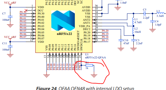
  2. Current peaks during BLE advertising (~13mA) do not change at all even though we change the transmission power from 0dBm to -20dBm. We don't enable the internal DC/DC converter because we are missing an external capacitor and inductor on the current version of the board. To the best of my understanding after reading Chapter 12 of the nRF51 reference manual, and Chapter 8.5 of nRF51822 Product Specification, using an internal DC/DC converter with 3.3V external supply voltage would help us reduce radio power to a factor of 0.65 - 0.8, depending on the used transmission power. Is my understanding correct?

Thanks in advance for your time and efforts.

Cheers,

Bojan.

Parents
  • Hello Bojan,

    The average current consumption between two BLE advertising cycles is ~1.6mA

    Are you in a debug session? Or have you been? Try stopping the debug session, then power cycle the nRF51 and do the measurement again. Does that lower the idle current consumption?

    Actually, on the topic, there were some issues with the nRF51 going into debug mode from time to time (without a debugger attached), so in the reference design we recommend adding an external 1k pulldown resistor on the SWDCLK pin. This is already mentioned in the reference designs:

    Are you measuring the current consumption on a DK or a custom board? If you are using a DK, did you cut the solderbridge SB9?

    Is my understanding correct?

    Yes. That seems about correct. 

    In case you haven't stumbled upon this, I find the Online Power Profiler quite useful for simulating the current consumption based on advertising/connection interval and the HW setup you are using. Check it out:

    https://devzone.nordicsemi.com/power/w/opp/2/online-power-profiler-for-bluetooth-le

    I see now that it is only supported for the nRF52 series and nRF53 series, but perhaps it can still give some idea in how intervals and DCDC affects the average current consumption.

    Best regards,

    Edvin

  • Hello,  .

    Thanks for your feedback.

    I have disabled debugging and both UART and RTT backends in sdk_config.h file (find it attached), power cycled the board after downloading the code, as you suggested, but the current consumption waveform is still the same. The board consumes ~1.6mA of current between two BLE advertising cycles.

    Are you measuring the current consumption on a DK or a custom board? If you are using a DK, did you cut the solderbridge SB9?

    I'm measuring current consumption on our custom-designed board and we have an external 1K pull-down resistor connected to the SWDCLK pin, as you suggested.

    As I already mentioned, when I put all the peripheral chips on the board in shutdown mode and nRF51 in System OFF mode, the measured current consumption is about ~100uA. When all the peripherals remain in the same shutdown mode but nRF51 is continuously advertising, current consumption between two BLE advertising cycles rises to ~1.6mA.  CPU usage between two BLE advertising cycles is 0%. I've confirmed this by enabling appropriate debug logs from Power Management Library. So what we have is that the board consumes ~100uA when nRF51 is in System OFF and ~1.6mA when nRF51 is in System ON sleep mode.

    We have a few nRF51 GPIOs that are floating. Perhaps the current is leaking through them if they are not properly configured? Do we need to explicitly configure them as inputs with pull-up or pull-down resistors enabled?

    Sincerely,

    Bojan.

    4885.sdk_config.h

  • bojan said:
    We have a few nRF51 GPIOs that are floating. Perhaps the current is leaking through them if they are not properly configured? Do we need to explicitly configure them as inputs with pull-up or pull-down resistors enabled?

    Hello,

    Yes. If you want to consume the minimum amount of power, you should reset the GPIOs that you have used. I am not sure where/how you configured them, but if that was through a peripheral, then you can try to use the "uninit" equivalent of the init function. Not all of these uninit/deinit functions do this properly, so check that the pin is correctly set back to the default state after you are done.

    You can check the register for the GPIO's PIN_CNF[n]. Please check the Reference Manual, Table 83 on page 68.

    A default pin configuration should be 0x00000002, which is the default (reset) value. This state is called "disconnected input"

    You can also read the register from your application using:

    unit32_t config = NRF_GPIO->PIN_CNF[0]; //this will read the pin configuration of P0.00. 

    Alternatively, you can read it out using a debugger and nrfjprog --memrd 0x50000700" to read P0.00. for pin N use the address: 0x50000700 + n*0x04

    Or, depending on what IDE you are using, you can probably set a breakpoint and monitor the peripheral registers. 

    Best regards,

    Edvin

Reply
  • bojan said:
    We have a few nRF51 GPIOs that are floating. Perhaps the current is leaking through them if they are not properly configured? Do we need to explicitly configure them as inputs with pull-up or pull-down resistors enabled?

    Hello,

    Yes. If you want to consume the minimum amount of power, you should reset the GPIOs that you have used. I am not sure where/how you configured them, but if that was through a peripheral, then you can try to use the "uninit" equivalent of the init function. Not all of these uninit/deinit functions do this properly, so check that the pin is correctly set back to the default state after you are done.

    You can check the register for the GPIO's PIN_CNF[n]. Please check the Reference Manual, Table 83 on page 68.

    A default pin configuration should be 0x00000002, which is the default (reset) value. This state is called "disconnected input"

    You can also read the register from your application using:

    unit32_t config = NRF_GPIO->PIN_CNF[0]; //this will read the pin configuration of P0.00. 

    Alternatively, you can read it out using a debugger and nrfjprog --memrd 0x50000700" to read P0.00. for pin N use the address: 0x50000700 + n*0x04

    Or, depending on what IDE you are using, you can probably set a breakpoint and monitor the peripheral registers. 

    Best regards,

    Edvin

Children
  • Hey, !

    It seems that the increased current consumption comes from the GPIOs! I used the nrf_gpio_cfg_default() function to set all GPIOs to the default state (disconnected inputs) before BLE advertising and here is what I get:

    Current consumption between two BLE advertising cycles goes down to ~100uA order of magnitude!

    It is now clear to me that it is quite important to properly handle GPIOs if we want to optimize the current consumption.

    Thanks once again for guiding me in the right direction.

    Cheers,

    Bojan.

Related