Unexpected PWM behavior

I need to generate a clean 10kHz sine wave. I tried using PWM (https://devzone.nordicsemi.com/f/nordic-q-a/89209/clarification-on-how-to-generate-a-10khz-sine-wave-with-pwm-and-dma), and it works, but it's hard to filter the resulting signal. Given the 16MHz clock limit, and the need to have a 10kHz sine, I can only use 40 values and 40 points in the LUT.

One of the ideas was to to use PDM instead of PWM. the nRF52840 doesn't have PDM out, nor a way to stream a sequence of bits using DMA (as far as I can tell).

I thought that I could use a PWM with only 2 pulse (possible values 0, 1, and 2) and with that build any stream of bits. It would be expensive in terms of memory (every 2 bits is stored in a 16 bit array), but would work for a 800 point LUT.

So I tried this:

#include <stdio.h>
#include <string.h>
#include "nrf_drv_pwm.h"
#include "app_util_platform.h"
#include "app_error.h"
#include "boards.h"
#include "bsp.h"
#include "app_timer.h"
#include "nrf_drv_clock.h"

#include "nrf_log.h"
#include "nrf_log_ctrl.h"
#include "nrf_log_default_backends.h"

static nrf_drv_pwm_t m_pwm = NRF_DRV_PWM_INSTANCE(0);

static void init_bsp()
{
    APP_ERROR_CHECK(nrf_drv_clock_init());
    nrf_drv_clock_lfclk_request(NULL);
    APP_ERROR_CHECK(app_timer_init());
}

static nrf_pwm_values_common_t /*const*/ m_demo_seq_values[] =
{
    1 | 0x8000,
    1 | 0x8000,
    1 | 0x8000,
    1 | 0x8000,
    1 | 0x8000,
    1 | 0x8000,
    1 | 0x8000,
    1 | 0x8000,
    1 | 0x8000,
    1 | 0x8000,
    1 | 0x8000,
    1 | 0x8000,
    1 | 0x8000,
    1 | 0x8000,
    1 | 0x8000,
    1 | 0x8000,
    1 | 0x8000,
    1 | 0x8000,
    1 | 0x8000,
    1 | 0x8000,
    1 | 0x8000,
    1 | 0x8000,
    1 | 0x8000,
    1 | 0x8000,
    1 | 0x8000,
    1 | 0x8000,
    1 | 0x8000,
    1 | 0x8000,
};

static void demo(void)
{
    static nrf_pwm_sequence_t const    m_demo_seq =
    {
        .values.p_wave_form  = &m_demo_seq_values,
        .length              = NRF_PWM_VALUES_LENGTH(m_demo_seq_values),
        .repeats             = 0,
        .end_delay           = 0
    };

    nrf_drv_pwm_config_t const config =
    {
        .output_pins =
        {
            ARDUINO_7_PIN, 
            NRFX_PWM_PIN_NOT_USED,
            NRFX_PWM_PIN_NOT_USED,
            NRFX_PWM_PIN_NOT_USED
        },
        .irq_priority = APP_IRQ_PRIORITY_LOWEST,
        .base_clock   = NRF_PWM_CLK_16MHz,
        .count_mode   = NRF_PWM_MODE_UP,
        .top_value    = 2,
        .load_mode    = NRF_PWM_LOAD_COMMON,
        .step_mode    = NRF_PWM_STEP_AUTO
    };
    APP_ERROR_CHECK(nrf_drv_pwm_init(&m_pwm, &config, NULL));
    (void)nrf_drv_pwm_simple_playback(&m_pwm, &m_demo_seq, 1,
                                      NRF_DRV_PWM_FLAG_LOOP);
}


int main(void)
{
    APP_ERROR_CHECK(NRF_LOG_INIT(NULL));
    NRF_LOG_DEFAULT_BACKENDS_INIT();
    init_bsp();

    demo();

    for (;;)
    {
        // Wait for an event.
        __WFE();
        // Clear the event register.
        __SEV();
        __WFE();
        NRF_LOG_FLUSH();
    }
}

but I got very weird results. On my scope, I see a single pulse at a ~490Hz frequency

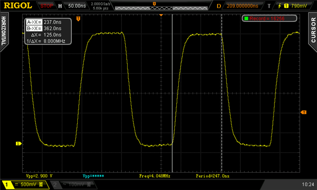
When I change the clock to 8MHz (.base_clock   = NRF_PWM_CLK_16MHz), clean signal as expected

My question is: am I using the SDK functions wrongly? Is there a way to make a 16MHz, two pulses, PWM signal work? Did I hit a hardware limitation?

  • Might be worth reviewing this erratum handling: nRF52_PAN_109_add_v1.1.pdf although I do not seem to be affected by this issue on Rev.2 silicon with bare-metal drivers. Nordic engineers would be better placed to comment further.

  • Thanks for the suggestion. I tried on two different SDK boards, one using a chip marked Q1AAC0, and the other Q1AAD0 (the nRF programmer identifies the former as REV1, the latter as REV2), and there is no difference

    I also tried modifying the PWM "bare metal" example you sent me a few days back (thanks again, really appreciate your PWM knowledge), but I see the exact same problem: with COUNTERTOP=3, I see a single pulse train at 16MHz, but with COUNTERTOP=2, same problem. Please note that I had to use PWM modeup, because with updown as in your example, the frequency of the pulse is 8MHz with a 16MHz clock (also changed the number of loops, to simplify the oscilloscope capture). Can you really get 16MHz pulses with COUNTERTOP=2 on your devices?

    Here's the code I used

    #define PWM_PIN (ARDUINO_7_PIN)
    #define PWM_STEPS 800
    uint16_t buf[PWM_STEPS];
    void TestPWM(void)
    {
      // Build (say) ramp - Ramp up/Down
      for (uint32_t i=0; i<PWM_STEPS; i++)
      {
         buf[i] = 0x8000 | 1; 
      }
      // Start crystal HFCLK
      NRF_CLOCK->TASKS_HFCLKSTART = 1;
      while (NRF_CLOCK->EVENTS_HFCLKSTARTED == 0) ;
      NRF_CLOCK->EVENTS_HFCLKSTARTED = 0;
      // Configure PWM_PIN as output, drive low
      NRF_GPIO->DIRSET = (1 << PWM_PIN);
      NRF_GPIO->OUTCLR = (1 << PWM_PIN);
      NRF_PWM0->PRESCALER   = PWM_PRESCALER_PRESCALER_DIV_1; // 16 MHz clock
      NRF_PWM0->PSEL.OUT[0] = PWM_PIN;
      NRF_PWM0->MODE        = (PWM_MODE_UPDOWN_Up << PWM_MODE_UPDOWN_Pos);
      NRF_PWM0->DECODER     = (PWM_DECODER_LOAD_Common << PWM_DECODER_LOAD_Pos) | (PWM_DECODER_MODE_RefreshCount << PWM_DECODER_MODE_Pos);
      NRF_PWM0->LOOP        = 100000;
      NRF_PWM0->COUNTERTOP = 2;
      NRF_PWM0->SEQ[0].CNT = ((sizeof(buf) / sizeof(uint16_t)) << PWM_SEQ_CNT_CNT_Pos);
      NRF_PWM0->SEQ[0].ENDDELAY = 0;
      NRF_PWM0->SEQ[0].PTR = (uint32_t)&buf[0];
      NRF_PWM0->SEQ[0].REFRESH = 0;
      NRF_PWM0->SEQ[1].CNT = ((sizeof(buf) / sizeof(uint16_t)) << PWM_SEQ_CNT_CNT_Pos);
      NRF_PWM0->SEQ[1].ENDDELAY = 0;
      NRF_PWM0->SEQ[1].PTR = (uint32_t)&buf[0];
      NRF_PWM0->SEQ[1].REFRESH = 0;
      // Stop after burst
      NRF_PWM0->SHORTS = NRF_PWM_SHORT_LOOPSDONE_STOP_MASK;
      NRF_PWM0->ENABLE = 1;
      NRF_PWM0->TASKS_SEQSTART[0] = 1;
    }

    I really think it's some sort of HW limitation

  • Confirmed. With the code above I see the same issue, fixed by using a divide-by-2 prescaler or a COUNTERTOP of > 2. It helps to set NRF_PWM0->SHORTS = 0x10011; to allow testing with a short pre-determined number of steps (say 8) and/or a short LOOP count.

    Nordic Team: looks similar to Errata 109 to me even without using sleep, meaning a value of 0 is incorrectly used on DMA bus fail. Same in Grouped or Common load.

    Edit: Using a complex sequence with PWM_DECODER_MODE_NextStep gives the exact same issue. With simple or complex note this slightly disturbibg item:

    "47.3 Limitations
    The previous compare value will be repeated if the PWM period is selected to be shorter than the time it takes for the EasyDMA to fetch from RAM and update the internal compare registers. This is to ensure a glitch-free operation even if very short PWM periods are chosen"

  • Appreciate you taking the time to repro and provide input

  • Hi there,

    I have very limited experience with look-up tables in regards to making sinus waves so I can't really offer that much help there.

    robca said:
    I also tried modifying the PWM "bare metal" example you sent me a few days back (thanks again, really appreciate your PWM knowledge), but I see the exact same problem: with COUNTERTOP=3, I see a single pulse train at 16MHz,

    Are you saying that you were able to produce a 16 MHz PWM signal with countertop = 3? What was the base clock and seq in this case?

    In regards to the PWM peripheral I would like state that the PWM peripheral runs at the 16 MHz clock, and should be able to theoretically support up to max 8 MHz. However from my own tests I see that the peripheral do not produce stable values at 8 MHz. I had to decrease the frequency down to 4 MHz to get a stable signal out. My suspicion is that we're looking at a limitation of the PWM peripheral and that it might be lower than I first expected. I have to discuss this with our HW developers. 

    Please expect some delay, as we're short on staff due to summer vacation.

    I'll be back with more.

    Thank you

    regards
    Jared 

Related