
I want to debug an application using J-Trace Pro from Segger and Ozone. I am using the nRF 5340 DK.
I used samples/basic/blinky project as a starting point from nRF Connect SDK v2.0.0, compiled with VScode.
I did the following modifications:
- Added CONFIG_NRF_TRACE_PORT=y in prj.conf file:
CONFIG_GPIO=y
CONFIG_NRF_TRACE_PORT=y
- Removed from nrf5340_cpuapp_common.dts button3, button4 and the flow control pins for the uart port to avoid conflicts with TRACEDATA pins
/*
 * Copyright (c) 2019-2020 Nordic Semiconductor ASA
 *
 * SPDX-License-Identifier: Apache-2.0
 */
#include "nrf5340_cpuapp_common-pinctrl.dtsi"

/ {

	chosen {
		zephyr,console = &uart0;
		zephyr,shell-uart = &uart0;
		zephyr,uart-mcumgr = &uart0;
		zephyr,bt-mon-uart = &uart0;
		zephyr,bt-c2h-uart = &uart0;
	};

	leds {
		compatible = "gpio-leds";
		led0: led_0 {
			gpios = <&gpio0 28 GPIO_ACTIVE_LOW>;
			label = "Green LED 0";
		};
		led1: led_1 {
			gpios = <&gpio0 29 GPIO_ACTIVE_LOW>;
			label = "Green LED 1";
		};
		led2: led_2 {
			gpios = <&gpio0 30 GPIO_ACTIVE_LOW>;
			label = "Green LED 2";
		};
		led3: led_3 {
			gpios = <&gpio0 31 GPIO_ACTIVE_LOW>;
			label = "Green LED 3";
		};
	};

	pwmleds {
		compatible = "pwm-leds";
		pwm_led0: pwm_led_0 {
			pwms = <&pwm0 0 PWM_MSEC(20) PWM_POLARITY_INVERTED>;
		};
	};

	buttons {
		compatible = "gpio-keys";
		button0: button_0 {
			gpios = <&gpio0 23 (GPIO_PULL_UP | GPIO_ACTIVE_LOW)>;
			label = "Push button 1";
		};
		button1: button_1 {
			gpios = <&gpio0 24 (GPIO_PULL_UP | GPIO_ACTIVE_LOW)>;
			label = "Push button 2";
		};
	};

	arduino_header: connector {
		compatible = "arduino-header-r3";
		#gpio-cells = <2>;
		gpio-map-mask = <0xffffffff 0xffffffc0>;
		gpio-map-pass-thru = <0 0x3f>;
		gpio-map = <0 0 &gpio0 4 0>,	/* A0 */
			   <1 0 &gpio0 5 0>,	/* A1 */
			   <2 0 &gpio0 6 0>,	/* A2 */
			   <3 0 &gpio0 7 0>,	/* A3 */
			   <4 0 &gpio0 25 0>,	/* A4 */
			   <5 0 &gpio0 26 0>,	/* A5 */
			   <6 0 &gpio1 0 0>,	/* D0 */
			   <7 0 &gpio1 1 0>,	/* D1 */
			   <8 0 &gpio1 4 0>,	/* D2 */
			   <9 0 &gpio1 5 0>,	/* D3 */
			   <10 0 &gpio1 6 0>,	/* D4 */
			   <11 0 &gpio1 7 0>,	/* D5 */
			   <12 0 &gpio1 8 0>,	/* D6 */
			   <13 0 &gpio1 9 0>,	/* D7 */
			   <14 0 &gpio1 10 0>,	/* D8 */
			   <15 0 &gpio1 11 0>,	/* D9 */
			   <16 0 &gpio1 12 0>,	/* D10 */
			   <17 0 &gpio1 13 0>,	/* D11 */
			   <18 0 &gpio1 14 0>,	/* D12 */
			   <19 0 &gpio1 15 0>,	/* D13 */
			   <20 0 &gpio1 2 0>,	/* D14 */
			   <21 0 &gpio1 3 0>;	/* D15 */
	};

	arduino_adc: analog-connector {
		compatible = "arduino,uno-adc";
		#io-channel-cells = <1>;
		io-channel-map = <0 &adc 0>,	/* A0 = P0.4 = AIN0 */
				 <1 &adc 1>,	/* A1 = P0.5 = AIN1 */
				 <2 &adc 2>,	/* A2 = P0.6 = AIN2 */
				 <3 &adc 3>,	/* A3 = P0.7 = AIN3 */
				 <4 &adc 4>,	/* A4 = P0.25 = AIN4 */
				 <5 &adc 5>;	/* A5 = P0.26 = AIN5 */
	};

	gpio_fwd: nrf-gpio-forwarder {
		compatible = "nordic,nrf-gpio-forwarder";
		status = "okay";
		uart {
			gpios = <&gpio1 1 0>, <&gpio1 0 0>;
		};
	};

	/* These aliases are provided for compatibility with samples */
	aliases {
		led0 = &led0;
		led1 = &led1;
		led2 = &led2;
		led3 = &led3;
		pwm-led0 = &pwm_led0;
		sw0 = &button0;
		sw1 = &button1;
		bootloader-led0 = &led0;
	};
};

&adc {
	status = "okay";
};

&gpiote {
	status = "okay";
};

&gpio0 {
	status = "okay";
};

&gpio1 {
	status = "okay";
};

&i2c1 {
	compatible = "nordic,nrf-twim";
	status = "okay";
	pinctrl-0 = <&i2c1_default>;
	pinctrl-1 = <&i2c1_sleep>;
	pinctrl-names = "default", "sleep";
};

&uart0 {
	status = "okay";
	current-speed = <115200>;
	pinctrl-0 = <&uart0_default>;
	pinctrl-1 = <&uart0_sleep>;
	pinctrl-names = "default", "sleep";
};

&pwm0 {
	status = "okay";
	pinctrl-0 = <&pwm0_default>;
	pinctrl-1 = <&pwm0_sleep>;
	pinctrl-names = "default", "sleep";
};

&qspi {
	status = "okay";
	pinctrl-0 = <&qspi_default>;
	pinctrl-1 = <&qspi_sleep>;
	pinctrl-names = "default", "sleep";
	mx25r64: mx25r6435f@0 {
		compatible = "nordic,qspi-nor";
		reg = <0>;
		/* MX25R64 supports only pp and pp4io */
		writeoc = "pp4io";
		/* MX25R64 supports all readoc options */
		readoc = "read4io";
		sck-frequency = <8000000>;
		label = "MX25R64";
		jedec-id = [c2 28 17];
		sfdp-bfp = [
			e5 20 f1 ff  ff ff ff 03  44 eb 08 6b  08 3b 04 bb
			ee ff ff ff  ff ff 00 ff  ff ff 00 ff  0c 20 0f 52
			10 d8 00 ff  23 72 f5 00  82 ed 04 cc  44 83 68 44
			30 b0 30 b0  f7 c4 d5 5c  00 be 29 ff  f0 d0 ff ff
		];
		size = <67108864>;
		has-dpd;
		t-enter-dpd = <10000>;
		t-exit-dpd = <35000>;
	};
};

&timer0 {
	status = "okay";
};

&timer1 {
	status = "okay";
};

&timer2 {
	status = "okay";
};

arduino_serial: &uart1 {
	compatible = "nordic,nrf-uarte";
	current-speed = <115200>;
	pinctrl-0 = <&uart1_default>;
	pinctrl-1 = <&uart1_sleep>;
	pinctrl-names = "default", "sleep";
};

arduino_i2c: &i2c1 {};

arduino_spi: &spi4 {
	compatible = "nordic,nrf-spim";
	cs-gpios = <&arduino_header 16 GPIO_ACTIVE_LOW>; /* D10 */
	pinctrl-0 = <&spi4_default>;
	pinctrl-1 = <&spi4_sleep>;
	pinctrl-names = "default", "sleep";
};

&flash0 {

	partitions {
		compatible = "fixed-partitions";
		#address-cells = <1>;
		#size-cells = <1>;

		boot_partition: partition@0 {
			label = "mcuboot";
			reg = <0x00000000 0x00010000>;
		};
		slot0_partition: partition@10000 {
			label = "image-0";
		};
		slot0_ns_partition: partition@50000 {
			label = "image-0-nonsecure";
		};
		slot1_partition: partition@80000 {
			label = "image-1";
		};
		slot1_ns_partition: partition@c0000 {
			label = "image-1-nonsecure";
		};
		scratch_partition: partition@f0000 {
			label = "image-scratch";
			reg = <0x000f0000 0xa000>;
		};
		storage_partition: partition@fa000 {
			label = "storage";
			reg = <0x000fa000 0x00006000>;
		};
	};
};

/ {

	reserved-memory {
		#address-cells = <1>;
		#size-cells = <1>;
		ranges;

		sram0_image: image@20000000 {
			/* Zephyr image(s) memory */
		};

		sram0_s: image_s@20000000 {
			/* Secure image memory */
		};

		sram0_ns: image_ns@20040000 {
			/* Non-Secure image memory */
		};
	};
};

/* Include partition configuration file */
#include "nrf5340_cpuapp_partition_conf.dts"
- Turned off the UART flow control using the switch SW7 from the nRF5340 DK.
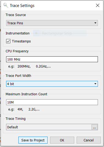
- Debug with Ozone, and configured the Trace Settings
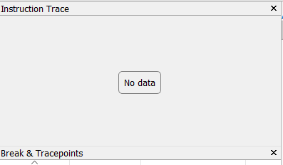
- After running the program the Instruction Trace view displays No data
When using Nordic_nRF5340_APP_TracePins.zip sample project from Segger the Instruction Trace work properly.
What other modifications should I do in order to be able to debug an application generated by the VScode, using Instruction Trace.


