nRF5340 Unable to configure I2S clock in passthrough mode

Hi,

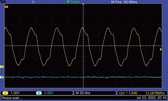
I'm having difficulty getting a clean MCK when configuring passthrough (bypass) mode. I'm using ACLK as the source and I do get a 12.288MHz signal on the MCK pin but it is only approximately 0.25Vp-p around a DC offset of ~2V. The waveform is triangular, not rectangular. Example screenshot attached at the bottom of this post.

I have tried both custom hardware and the PCA10095 DK board and get the same result on both boards.  For the custom board, MCK is on pin P0.05; for the DK board, I used P0.31.

To set the device up, I have the following code:

Start ACLK:

    nrf_clock_hfclkaudio_config_set(NRF_CLOCK_S, 0x9BA6); /* 12.288005MHz = 0.0004% error */
    nrf_clock_event_clear(NRF_CLOCK_S, NRF_CLOCK_EVENT_HFCLKAUDIOSTARTED);
    nrf_clock_task_trigger(NRF_CLOCK_S, NRF_CLOCK_TASK_HFCLKAUDIOSTART);

    while (!nrf_clock_event_check(NRF_CLOCK_S, NRF_CLOCK_EVENT_HFCLKAUDIOSTARTED));
    nrf_clock_event_clear(NRF_CLOCK_S, NRF_CLOCK_EVENT_HFCLKAUDIOSTARTED);

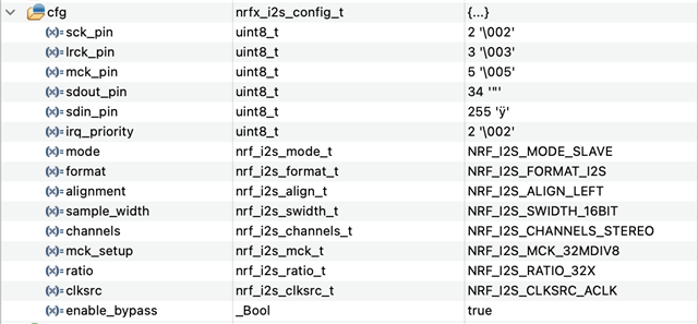
The I2S initialisation (&cfg) block being passed in is:

    err = nrfx_i2s_init(&cfg, palI2sCompHandler);
    PAL_SYS_ASSERT(err == NRFX_SUCCESS);

I have tried configuring the pin drive level in the GPIO peripheral immediately before the I2S peripheral is enabled but this has had no effect:

        nrf_gpio_cfg(
                (NRF_GPIO_PIN_MAP(0, 5)),
                NRF_GPIO_PIN_DIR_OUTPUT,
                NRF_GPIO_PIN_INPUT_DISCONNECT,
                NRF_GPIO_PIN_NOPULL,
                NRF_GPIO_PIN_H0H1,
                NRF_GPIO_PIN_NOSENSE
                );
        nrf_gpio_pin_set((NRF_GPIO_PIN_MAP(0, 5)));

        err = nrfx_i2s_start(&palI2sCb.initBuf[0], len / sizeof(uint32_t), 0);  /* length of data in words */
        PAL_SYS_ASSERT(err == NRFX_SUCCESS);

For reference, this is the clock signal (blue trace) that I am seeing (on the DK board the signal is about twice the amplitude and is more of a sawtooth):

Any assistance would be greatly appreciated.

Regards,

AC

  • Hi,

    Please disregard the above comments.

    I've looked at the issue again this time using a Tektronix 'scope (previous analysis was using a PicoScope 'scope) and I'm seeing very different results.

    To summarise, I can get a clean 12.288MHz signal on MCK on the three PCA10095 boards. I cannot get a clean 12.288MHz signal on the two custom boards and, on one custom board, the frequency is drifting between 11.5MHz and 12.6MHz.

    My first guess is that the PCB layout is a problem but the other difference is the silicon revision levels.  Device markings are as follows:

    • PCA10095 boards: QKAADB 2041AA
    • Custom boards: QKAAD0 2104AD

    I have read through the device errata and I do not see any item listed that relates to pin drive or clock issues. Can I ask if there are any known differences between the two silicon revisions listed above that might cause the signal degradation?

    For reference, here are screenshots of the 12.288MHz signal:

    Custom board:

    PCA10095 board:

    Kind regards,

    AC

  • Hello AC,

    Thank you for your patience with this. The summer holiday season has begun here in Norway, and so the DevZone forum is operating at reduced capacity for the next couple of weeks.

    Thank you for providing the additional information as well. This does indeed look like an issue with the custom hardware - there should be no differences between the revisions other than what is mentioned in the erratas. Additionally, your custom hardware is using a newer chip revision than the PCA10095, which strengthens the suspicion of the hardware.

    Please know that we can perform a schematic review for you if you would like, just let us know!
    If you would like us to, please open a separate, private ticket to request the schematic review. As mentioned, it might take a little longer to process due to the national holiday season.

    Best regards,
    Karl

Related