SPI chip select lines

I am trying to use a SPI bus with three MAX3109 chips attached to give me 6 UARTS. My overlay is defined as follows:

&spi1 {
    cs-gpios = <&gpio1 13 GPIO_ACTIVE_LOW>,
               <&gpio1 14 GPIO_ACTIVE_LOW>,
               <&gpio1 15 GPIO_ACTIVE_LOW>;
    status = "okay";
    sck-pin = <42>;
    mosi-pin = <43>;
    miso-pin = <44>;
    irda_uart0: irda_uart@0 {
        compatible = "spi-device";
        reg = <0>;
        status = "okay";
        label = "IRDA_UART0";
        spi-max-frequency = < 2000000 >;
      };
    irda_uart1: irda_uart@1 {
      compatible = "spi-device";
      reg = <1>;
      status = "okay";
      label = "IRDA_UART1";
      spi-max-frequency = < 2000000 >;
    };
    irda_uart2: irda_uart@2 {
      compatible = "spi-device";
      reg = <2>;
      status = "okay";
      label = "IRDA_UART2";
      spi-max-frequency = < 2000000 >;
    };
};
 
I then initialize the SPI configuration to test one of the devices as:
const struct spi_cs_control *cs_pin = SPI_CS_CONTROL_PTR_DT(DT_NODELABEL(irda_uart2), 2);

static const struct spi_config spi_cfg = {
    .operation = SPI_WORD_SET(8) | SPI_TRANSFER_MSB |
             SPI_MODE_CPOL | SPI_MODE_CPHA,
    .frequency = 2000000,
    .slave = 0,
    .cs = &cs_pin,
};
If I then call the following:
err = spi_transceive(spi_dev, &spi_cfg, &tx, &rx);
I can see on the scope that I have lost control of the SPI lines completely. However, if I comment out the cs pin assignment in the  configuration - i.e.:
static const struct spi_config spi_cfg = {
    .operation = SPI_WORD_SET(8) | SPI_TRANSFER_MSB |
             SPI_MODE_CPOL | SPI_MODE_CPHA,
    .frequency = 2000000,
    .slave = 0,
    // .cs = &cs_pin,
};
With no other changes to the code, I recompile and flash the device. Now I can see the CLK and MOSI lines exactly as expected, but of course I don't have the CS line working. I suppose I could just bit-bang the CS lines with GPIO calls, but why doesn't this arrangement work?
Thanks,
Jamie
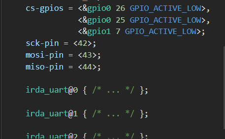
  • One thing I noticed - when I hover over the &spi1 in my overlay file to expand its contents, I see that it has added the cs-gpios information and pin assignments from the overlay. But the irda_uart nodes are showing that content automatically commented out. It seems that everything I define in there is being discarded, yet I'm not getting errors or warnings. See below.
  • Hi,

    Could you provide zephyr.dts file which is located in <your_application_folder>\build\zephyr?

    Could you please provide more information about "spi-device" that is present in your overlay file?

    Best regards,
    Dejan

  • Hi. I was able to make this work by changing the declaration of the spi_config struct a bit to just directly use the device tree macro SPI_CS_CONTROL_PTR_DT(). So I do the following:

    static const struct spi_config spi_cfg0 = {
        .operation = SPI_WORD_SET(8) | SPI_TRANSFER_MSB |
                 SPI_MODE_CPOL | SPI_MODE_CPHA,
        .frequency = 2000000,
        .slave = 0,
        .cs = SPI_CS_CONTROL_PTR_DT(DT_NODELABEL(irda_uart0), 2),
    };
    I can also target the other CS pin by creating a second struct: 
    static const struct spi_config spi_cfg1 = {
        .operation = SPI_WORD_SET(8) | SPI_TRANSFER_MSB |
                 SPI_MODE_CPOL | SPI_MODE_CPHA,
        .frequency = 2000000,
        .slave = 0,
        .cs = SPI_CS_CONTROL_PTR_DT(DT_NODELABEL(irda_uart1), 2),
    };
    I test this with the following:
        if(ping_pong) {
            ping_pong = false;
            err = spi_transceive(spi_dev, &spi_cfg0, &tx, &rx);
        } else {
            ping_pong = true;
            err = spi_transceive(spi_dev, &spi_cfg1, &tx, &rx);
        }
    And can see on the scope, triggering off the clock line, that the chip select pins alternate. So all good there. However, it might be worth mentioning that the delay time specified in the macro is completely ignored. Regardless of what I put there - I've tried values from 1 to 10 - the timing on chip select is always the same. CS line is pulled low 10usec before the clock starts and then pulled high 30usec after clock ends. This timing is fine and fact specifying a chip select delay for a SPI in msec is somewhat ludicrous in the first place. But I'm curious what that delay parameter actually controls.
    -Jamie
  • Hi,

    jmilliken said:
    it might be worth mentioning that the delay time specified in the macro is completely ignored.

    Which macro do you refer to?

    jmilliken said:
    Regardless of what I put there - I've tried values from 1 to 10 - the timing on chip select is always the same.

    Could you please show where and how you specify delay values?

    Best regards,
    Dejan

  • Hi. I am referring to the macro SPI_CS_CONTROL_PTR_DT(DT_NODELABEL(irda_uart1), 2). Jumping to the definition of the macro gives me the following:

     * @param node_id Devicetree node identifier for a device on a SPI bus
     * @param delay_ The @p delay field to set in the @p spi_cs_control
     * @return a pointer to the @p spi_cs_control structure
     */
    #define  SPI_CS_CONTROL_PTR_DT(node_id, delay_)           \
        (&(struct spi_cs_control) {               \
            .gpio = DT_SPI_DEV_CS_GPIOS_DT_SPEC_GET(node_id), \
            .delay = (delay_),                \
        })
    So this delay does not seem to be used, or at least I don't understand how it is used. Changing the value does not seem to make a difference in the outcome.
Related