

Hi!
I'm working on direction finding using nrf connect sdk.
I have already make a tx (nrf52833) and a rx (nrf52833) and i succeed to receive the CTE and the IQ sampling with the antenna onboard, but confused about switch pattern.
According the white book, the available IQ sample started from entry 3 and loop until the entire CTE period is over.
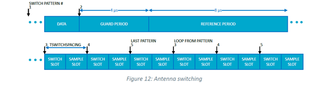
Q1: So, I assumed i need discard the first 8 values and use sample data from entry 9 (from 3th antenna in pattern) for futher caculate? The first two antennas never switched in the loop?
Q2: If so, will it affect subsequent sampling? The next IQ data will start from the 12th(9+3) antenna if the last IQ value was sampled from the 9th?
PER_ADV_SYNC[0]: [DEVICE]: 15:55:62:5B:84:69 (random), tx_power 127, RSSI -68, CTE AOA, data length 0, data:
CTE[0]: samples count 45, cte type AOA, slot durations: 2 [us], packet status CRC OK, RSSI -680
IQ sample content :
9,-4
-10,5
8,-4
-9,4
8,-4
-9,2
9,-4
-9,4
8,7
5,6
6,3
-2,-7
…
…
…
4,-6 // sampled from the 9th
PER_ADV_SYNC[0]: [DEVICE]: 15:55:62:5B:84:69 (random), tx_power 127, RSSI -72, CTE AOA, data length 0, data:
CTE[0]: samples count 45, cte type AOA, slot durations: 2 [us], packet status CRC OK, RSSI -720
IQ sample content :
-4,8
2,-9
-4,8
5,-9
-4,8
4,-8
-4,7
3,-9
-9,2 // sampled from the 12th ??
…
Antenna patterns:

