The sequence of Antenna switch pattern for Nrf52833

Hi! 

I'm working on direction finding using nrf connect sdk. 

I have already make a tx (nrf52833) and a rx (nrf52833) and i succeed to receive the CTE and the IQ sampling with the antenna onboard, but confused about switch pattern. 

According the white book, the available IQ sample started from entry 3 and loop until the entire CTE period is over.
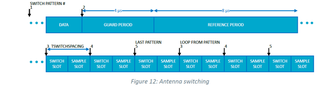
Q1: So, I assumed i need discard the first 8 values and use sample data from entry 9 (from 3th antenna in pattern) for futher caculate? The first two antennas never switched in the loop?

Q2: If so, will it affect subsequent sampling? The next IQ data will start from the 12th(9+3) antenna if the last IQ value was sampled from the 9th?

PER_ADV_SYNC[0]: [DEVICE]: 15:55:62:5B:84:69 (random), tx_power 127, RSSI -68, CTE AOA, data length 0, data:

CTE[0]: samples count 45, cte type AOA, slot durations: 2 [us], packet status CRC OK, RSSI -680

IQ sample content :

9,-4

-10,5

8,-4

-9,4

8,-4

-9,2

9,-4

-9,4

8,7

5,6

6,3

-2,-7

4,-6   // sampled from the 9th


PER_ADV_SYNC[0]: [DEVICE]: 15:55:62:5B:84:69 (random), tx_power 127, RSSI -72, CTE AOA, data length 0, data:

CTE[0]: samples count 45, cte type AOA, slot durations: 2 [us], packet status CRC OK, RSSI -720

IQ sample content :

-4,8

2,-9

-4,8

5,-9

-4,8

4,-8

-4,7

3,-9

-9,2   // sampled from the 12th ??

Antenna patterns:

    static const uint8_t ant_patterns[] = { 0x2, 0x0, 0x5, 0x6, 0x1, 0x4,0xC, 0x9, 0xE, 0xD, 0x8, 0xA };
  • Hi,

    Our experts on this are out of office right now, but I will check internally and get back to you.

    Best regards,

    Marte

  • Hi,

    No data should be discarded, and discarding the first 8 readings will guarantee that your solution does not work. Please read up on how to convert from CTE data to phase change to understand how this is done.

    The first 8 samples are used to get the:

    • Frequency of the incoming signal
    • Signal strength of the reference antenna
    • Reference phase of the incoming signal, all other samples are referenced against this signal

    Without this reference data there is no way to get the phase shift for the other antennas in the matrix.

    The input table has 1 value for the standard Bluetooth Low Energy packet section (pattern 1), one for the reference period (pattern 2, 8 IQ samples), we use the same antenna for both of these in our samples. The 9th IQ sample is for pattern entry 3, the 10th IQ sample for pattern entry 4 and so on.

    If you are to make a Bluetooth compliant solution then the pattern should always rotate through the reference antenna, this can be done by having the reference antenna (pattern entry 2) as the last entry in the pattern table. It will then be part of the "looped" pattern.
    When you have gone through all the patterns loaded then the next IQ sample will be from pattern 3 and this will loop for the length of the CTE duration.

    Best regards,

    Marte

  • Hi Marte,


    Thanks for your reply.

    The input table has 1 value for the standard Bluetooth Low Energy packet section (pattern 1), one for the reference period (pattern 2, 8 IQ samples), we use the same antenna for both of these in our samples. The 9th IQ sample is for pattern entry 3, the 10th IQ sample for pattern entry 4 and so on.

    If you use the same one antenna for standard BLE packet and reference period, it means the 9th IQ sample is for entry 2 in pattern? 

    If you are to make a Bluetooth compliant solution then the pattern should always rotate through the reference antenna, this can be done by having the reference antenna (pattern entry 2) as the last entry in the pattern table. It will then be part of the "looped" pattern.
    When you have gone through all the patterns loaded then the next IQ sample will be from pattern 3 and this will loop for the length of the CTE duration.

    For Q2, you mean the next reference antenna should be entry 2 pattern in next sample loop, and the first sample will be from entry 3.  Loop in the following way until Periodic sync lost? 

    PER_ADV_SYNC[0]: [DEVICE]: 15:55:62:5B:84:69 (random) synced, Interval 0x0780 (2400 ms), PHY LE 2M
    PER_ADV_SYNC[0]: [DEVICE]: 15:55:62:5B:84:69 (random), tx_power 127, RSSI -83, CTE AOA, data length 0, data:
    success. Periodic sync established.
    Enable receiving of CTE...
    success. CTE receive enabled.
    Scan disable...Success.
    Waiting for periodic sync lost...

    ...

    4,-6   // the last one sampled from the 2th antenna

    PER_ADV_SYNC[0]: [DEVICE]: 15:55:62:5B:84:69 (random), tx_power 127, RSSI -72, CTE AOA, data length 0, data:

    CTE[0]: samples count 45, cte type AOA, slot durations: 2 [us], packet status CRC OK, RSSI -720

    IQ sample content :

    -4,8

    3,-9    // 8 samples from the 2th in reference period

    -9,2   // sampled from the 3th?

    ...

    PER_ADV_SYNC[0]: [DEVICE]: 15:55:62:5B:84:69 (random) sync terminated
    Periodic sync lost.

  • Hi,

    Ben_M said:
    If you use the same one antenna for standard BLE packet and reference period, it means the 9th IQ sample is for entry 2 in pattern? 

    No, the 9th IQ sample will be pattern 3 as I stated. The first pattern is used for the data part of the packet, i.e. standard Bluetooth Low Energy packet section, and the second pattern is for the guard and reference periods, regardless of whether the same antenna is used for both or not.

    Ben_M said:
    For Q2, you mean the next reference antenna should be entry 2 pattern in next sample loop, and the first sample will be from entry 3.  Loop in the following way until Periodic sync lost? 

    No, the next loop will not have patterns 1 and 2. It loops back and starts from the one used in the first switch slot, which will be pattern 3. That is why the reference antenna should be the last pattern entry, so that it will loop through it. 

    Imagine you have three antennas: the reference antenna, antenna 2 and antenna 3, and the patterns are divided as this:

    Pattern Antenna
    1 Reference antenna Data
    2 Reference antenna Guard + reference period
    3 Antenna 2 Switch slot + switch sample
    4 Antenna 3 Switch slot + switch sample
    5 Reference antenna Switch slot + switch sample

    The antenna switching will then look like this:

    So the pattern loop is 1 → 2 → 3 → 4 → 5 → 3 → 4 → 5 → 3 → 4 → 5 → 3 and so on.

    Best regards,

    Marte

  • I see... Thanks for your detailed interpret!

    One more question: 

    When the last sample finished in the CTE period, will the antenna automatically switch back to the ref antenna? Or stay the last antenna?

Related
