Synchronizing the multiple PWM pulses using the DPPI interface

Hi,

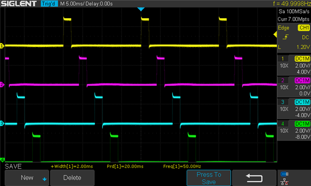
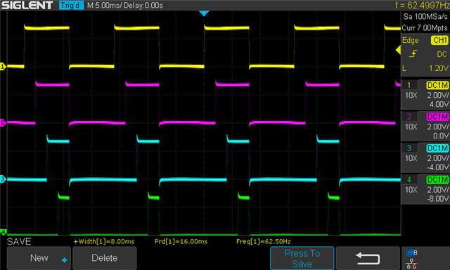
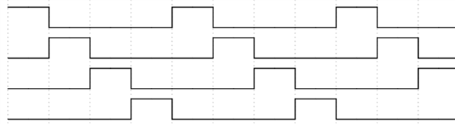
I want to set up a set of four PWM signals that are delayed at a specified interval, just like how the stepper motors are run but the falling edge of the previous channel signal does not need to be in sync with the rising edge of the next channel signal.

So far, I was able to toggle multiple GPIO pins using a single timer task and multiple GPIO pin events, but those pins always toggle on and off simultaneously. I found this Github repo, but this is for the PPI interface on the nRF52 series. Do you have a similar sample/example for the DPPI interface on the nRF5340? I am having trouble switching the SUBSCRIBE_OUT to SUBSCRIBE_SET and SUBSCRIBE_CLR in the DPPI channel...

In summary, my question is:

1. Can I use a single timer to make four synchronized PWM signals spaced out at a specific interval, or do I need to use all individual timers for each I/O?

2. In the DPPI interface, I am having trouble enabling multiple timer compare channels... Can I use this line to set multiple channels on the same timer?

nrfx_timer_extended_compare(&timer1, NRF_TIMER_CC_CHANNEL0, nrfx_timer_us_to_ticks(&timer1, 1000000), NRF_TIMER_SHORT_COMPARE0_CLEAR_MASK, false);
nrfx_timer_extended_compare(&timer1, NRF_TIMER_CC_CHANNEL1, nrfx_timer_us_to_ticks(&timer1, 1000), NRF_TIMER_SHORT_COMPARE1_CLEAR_MASK, false);
nrfx_timer_extended_compare(&timer1, NRF_TIMER_CC_CHANNEL2, nrfx_timer_us_to_ticks(&timer1, 500), NRF_TIMER_SHORT_COMPARE2_CLEAR_MASK, false);

3. My biggest concern is how to start each PWM channel in a synchronized way. Is there any helper layer that allows this?

Thanks!

Ted

Parents Reply Children
  • Yes, the ADC read must be triggered when any of these pulses rise and fall.

  • Ok, if you use the PWM peripheral, you have some events like EVENTS_SEQEND, EVENTS_SEQSTARTED and EVENTS_PWMPERIODEND that you could use to trigger the read.

    I found this Github repo, but this is for the PPI interface on the nRF52 series. Do you have a similar sample/example for the DPPI interface on the nRF5340? I am having trouble switching the SUBSCRIBE_OUT to SUBSCRIBE_SET and SUBSCRIBE_CLR in the DPPI channel...

    The example is not ported to the nRF53, but if try to do that, I recommend looking at the nrfx_gppi_* functions. They are used e.g. in this sample: https://github.com/nrfconnect/sdk-zephyr/blob/v3.0.99-ncs1/samples/boards/nrf/nrfx/src/main.c

  • I think I found a way to make the 4 PWM signals from 4 GPIOTE pins with two timers by assigning two PWM signals to each timer. There are only 6 DPPI channels available, so I could only fit 3 PWM signals within a single timer.

    I guess this scope image should help you understand what I intended to demonstrate here:

    Here is how I set up two timers:

    static void timer1_init(void)
    {
    	nrfx_err_t err = NRFX_SUCCESS;
    	nrfx_timer_config_t timer_cfg = NRFX_TIMER_DEFAULT_CONFIG;
    	timer_cfg.bit_width = NRF_TIMER_BIT_WIDTH_32;
    
    	err = nrfx_timer_init(&timer1, &timer_cfg, timer1_evt_handler);
    	if(err != NRFX_SUCCESS)
    	{
    		LOG_ERR("Error! Could not initialize TIMER1: %d\n", err);
    	}
    
    	nrfx_timer_extended_compare(&timer1, NRF_TIMER_CC_CHANNEL0, nrfx_timer_us_to_ticks(&timer1, 16000), NRF_TIMER_SHORT_COMPARE0_CLEAR_MASK, false);    // Reload
    	nrfx_timer_extended_compare(&timer1, NRF_TIMER_CC_CHANNEL1, nrfx_timer_us_to_ticks(&timer1, 2000), NRF_TIMER_SHORT_COMPARE0_CLEAR_MASK, false);     // First GPIOTE pin set @ 2 ms
    	nrfx_timer_extended_compare(&timer1, NRF_TIMER_CC_CHANNEL2, nrfx_timer_us_to_ticks(&timer1, 4000), NRF_TIMER_SHORT_COMPARE0_CLEAR_MASK, false);     // First GPIOTE pin clear @ 4 ms
    	nrfx_timer_extended_compare(&timer1, NRF_TIMER_CC_CHANNEL3, nrfx_timer_us_to_ticks(&timer1, 6000), NRF_TIMER_SHORT_COMPARE0_CLEAR_MASK, false);     // Second GPIOTE pin set @ 6 ms
    	nrfx_timer_extended_compare(&timer1, NRF_TIMER_CC_CHANNEL4, nrfx_timer_us_to_ticks(&timer1, 8000), NRF_TIMER_SHORT_COMPARE0_CLEAR_MASK, false);     // Second GPIOTE pin clear @ 8 ms
    	nrfx_timer_extended_compare(&timer1, NRF_TIMER_CC_CHANNEL5, nrfx_timer_us_to_ticks(&timer1, 20000), NRF_TIMER_SHORT_COMPARE0_CLEAR_MASK, false);    // Not used
    }
    
    static void timer2_init(void)
    {
    	nrfx_err_t err = NRFX_SUCCESS;
    	nrfx_timer_config_t timer_cfg = NRFX_TIMER_DEFAULT_CONFIG;
    	timer_cfg.bit_width = NRF_TIMER_BIT_WIDTH_32;
    
    	err = nrfx_timer_init(&timer2, &timer_cfg, timer2_evt_handler);
    	if(err != NRFX_SUCCESS)
    	{
    		LOG_ERR("Error! Could not initialize TIMER1: %d\n", err);
    	}
    
    	nrfx_timer_extended_compare(&timer2, NRF_TIMER_CC_CHANNEL0, nrfx_timer_us_to_ticks(&timer1, 16000), NRF_TIMER_SHORT_COMPARE0_CLEAR_MASK, false);    // Reload
    	nrfx_timer_extended_compare(&timer2, NRF_TIMER_CC_CHANNEL1, nrfx_timer_us_to_ticks(&timer1, 10000), NRF_TIMER_SHORT_COMPARE0_CLEAR_MASK, false);    // Third GPIOTE pin set @ 10 ms
    	nrfx_timer_extended_compare(&timer2, NRF_TIMER_CC_CHANNEL2, nrfx_timer_us_to_ticks(&timer1, 12000), NRF_TIMER_SHORT_COMPARE0_CLEAR_MASK, false);    // Third GPIOTE pin clear @ 12 ms
    	nrfx_timer_extended_compare(&timer2, NRF_TIMER_CC_CHANNEL3, nrfx_timer_us_to_ticks(&timer1, 14000), NRF_TIMER_SHORT_COMPARE0_CLEAR_MASK, false);    // Fourth GPIOTE pin set @ 14 ms
    	nrfx_timer_extended_compare(&timer2, NRF_TIMER_CC_CHANNEL4, nrfx_timer_us_to_ticks(&timer1, 16000), NRF_TIMER_SHORT_COMPARE0_CLEAR_MASK, false);    // Fourth GPIOTE pin clear @ 16 ms
    	nrfx_timer_extended_compare(&timer2, NRF_TIMER_CC_CHANNEL5, nrfx_timer_us_to_ticks(&timer1, 20000), NRF_TIMER_SHORT_COMPARE0_CLEAR_MASK, false);    // Not used
    }

    I figured I could set 4 PWM signals within a single timer if they either start/stop at the same time, just like this:

    Would it be the same if I used the PWM peripheral? I couldn't find a way to start the PWM signal in a delayed manner when I used the PWM peripheral so I don't know if the PWM peripheral offers something like I first presented in this reply. It would be great if I could get the PWM peripheral to do this directly and get 4 PWM signals from a single PWM instance since I plan to expand this setup to more channels later on.

    Thanks!

Related