PWM pin floating (even with NRFX_PWM_PIN_INVERTED)

Hi,

I'm testing a prototype with the nRF52840 where I drive a buzzer in the following way:

PWM schematic

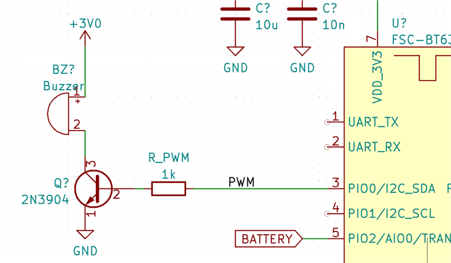
When I play a signal, I see that the current through the buzzer is about 14mA, which seems reasonable. I do this by writing 0x01 to a characteristic.

The audio only plays for less than 1 second. However, the current remains the same even when it's at silence. The VBE of the 2N3904 is at 0.46V approx.

However, if I use nrfx_pwm_stop(&m_pwm, false) (by writing 0x00 to the characteristic), then the current through the buzzer goes up to 114mA! Measuring Vbe, I find that it's now at 1.1V, which is for sure the cause of the problem.

Obviously, the solution is to put a pull-down resistor at this pin.

The question is: is there a way to handle this within the library?

I'm actually initializing the pin with the NRFX_PWM_PIN_INVERTED, which should pull the pin down, nominally. However, for some reason, this isn't working when stopping the tone.
This is the code with which I initialize the PWM module:

  nrfx_pwm_config_t const pwm_config= 
  {
    .output_pins  = { gpio_pin | NRFX_PWM_PIN_INVERTED,
                      NRFX_PWM_PIN_NOT_USED,
                      NRFX_PWM_PIN_NOT_USED,
                      NRFX_PWM_PIN_NOT_USED },
    .irq_priority = NRF_PWM_AUDIO_PRIORITY,
    .base_clock   = NRF_PWM_CLK_16MHz,
    .count_mode   = NRF_PWM_MODE_UP,
    .top_value    = NRF_PWM_AUDIO_COUNTERTOP,
    .load_mode    = PWM_DECODER_LOAD_Common,
    .step_mode    = PWM_DECODER_MODE_RefreshCount      
  };

Thanks in advance for your help!

Parents
  • Generating a Stop will release the pins into normal PIO mode, so before initialising the PWM first set that pin to an output and drive it low; then after the Stopped event that pin will revert to a '0' output and turn the transistor off.

    "To completely stop the PWM generation and force the associated pins to a defined state, a STOP task can be triggered at any time. A STOPPED event is generated when the PWM generation has stopped at the end of currently running PWM period, and the pins go into their idle state as defined in GPIO OUT register"

    Since the buzzer is a piezo device it consumes little power; by putting the PWM into H-Bridge driver mode you can double the output voltage swing from 3V to 6V. Two pins are required, one driving each end of the piezo. Remove the +3V0 connection and throw away the resistor and transistor.. The second pin should use the same data as the first but with the inverted bit set.

Reply
  • Generating a Stop will release the pins into normal PIO mode, so before initialising the PWM first set that pin to an output and drive it low; then after the Stopped event that pin will revert to a '0' output and turn the transistor off.

    "To completely stop the PWM generation and force the associated pins to a defined state, a STOP task can be triggered at any time. A STOPPED event is generated when the PWM generation has stopped at the end of currently running PWM period, and the pins go into their idle state as defined in GPIO OUT register"

    Since the buzzer is a piezo device it consumes little power; by putting the PWM into H-Bridge driver mode you can double the output voltage swing from 3V to 6V. Two pins are required, one driving each end of the piezo. Remove the +3V0 connection and throw away the resistor and transistor.. The second pin should use the same data as the first but with the inverted bit set.

Children
No Data
Related