Uart communication between nrf52832 dev kit and another MCU.

Good Morning people.
I'm developing a module with the soic nrf52832 and I'm having doubts about the electrical schematic of the UART communication with another MCU.
I analyzed the electrical schematic of the PCA10040-nRF52832 development kit and realized that only pins P0.05(RTS), P0.06(TXD), P0.07(CTS) and P0.08(RXD) are used for serial communication.
In my case I'll have to use all these pins or just need to consider the TX and RX pins.
And for what server the RTS and CTS?

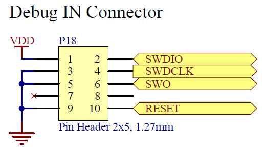
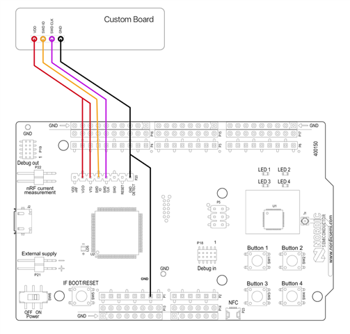
My other question is if it is possible to use the development kit as a recorder of the module that I am developing, I saw that there is a Debug in pins?


  • you can connect the pins like this


    But the cts & rts are not mandatory nowadays (they are from the past where device where much slower, they are handshake signals.)

    some more information:
    https://www.codrey.com/embedded-systems/rs232-serial-communication/


    About the second question:
    yes, you can use another development kit as a recorder (spy-monitor)  just google on rs232 splitter cable pintout    


    note: understand the difference between
      dce-dce connection (computer to computer)  versus  dce-dte (computer to peripheral)
     they are the reason the pinout schema's show cross-connections or straight connections

  • Thank you for informacion.

    So just use RX, TX and GND for serial communication via UART.

    Regarding the recorder, I want to use the Debug In Connect pins, pins 2, 4, VCC and GND. to write to the module that I am developing, as shown in the image below

    I'm trying this possibility to test the module in the future we are going to buy the segger programming recorder.

  • Hello,

    nrf5xfanboy is correct about the CTS/RTS pins - they are most useful these days if you will be communicating at very high speeds with a system that is not always ready to receive the incoming data, for instance.

    I am not sure if I understood your 'recorder' question correctly but you can indeed use the development kit as a debugger for your other SoC through the SWD interface. I have attached an image that shows how this can be done:


    For convenience I would recommend that you program your DK with the regular 'blinky' example before you use it as the debugger for your other SoC, so that you can easily verify that the program was written to the correct Chip (since the DK should keep blinking as usual).

    Best regards,
    Karl

Related