Hello,
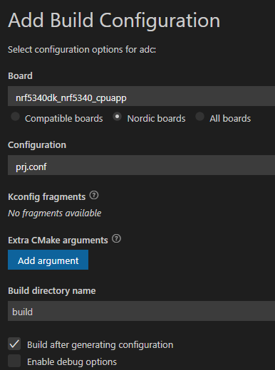
nRF5340+nRF21540, NCS2.0.2, vscode.
Hello,
nRF5340+nRF21540, NCS2.0.2, vscode.
Hi,
There is two errata regarding the current draw in power down state for the nRF21540, Errata 13 and Errata 14.
Errata 13 may be the cause of this increased current consumption while in sleep mode. If any of the input pins are set high during sleep there will in some cases be a increase up to 500uA while in power down. The workaround for this is to make sure all the input pins( CSN, RX_EN, TX_EN, MODE, SCK, MOSI and ANT_SEL) are set low when entering sleep.
Best regards,
Bendik
Hi,
There is two errata regarding the current draw in power down state for the nRF21540, Errata 13 and Errata 14.
Errata 13 may be the cause of this increased current consumption while in sleep mode. If any of the input pins are set high during sleep there will in some cases be a increase up to 500uA while in power down. The workaround for this is to make sure all the input pins( CSN, RX_EN, TX_EN, MODE, SCK, MOSI and ANT_SEL) are set low when entering sleep.
Best regards,
Bendik
Hi,
thanks for reply, you are right.
i set PDN low, it will work well,
another question, how to set 21540 TX max power, and RX min power?
CSN connect to VDD. use GPIO mode.
demo\boards\nrf5340dk_nrf5340_cpuapp.overlay
/{
pdn_21540: pdn_21540_ {
status = "okay";
gpios = < &gpio1 0x0b GPIO_ACTIVE_HIGH >;
label = "pdn_21540";
};
csn_21540: csn_21540_ {
status = "okay";
gpios = < &gpio1 0x0c GPIO_ACTIVE_HIGH >;
label = "csn_21540";
};
txen_21540: txen_21540_ {
status = "okay";
gpios = < &gpio1 0x07 GPIO_ACTIVE_HIGH >;
label = "txen_21540";
};
rxen_21540: rxen_21540_ {
status = "okay";
gpios = < &gpio1 0x05 GPIO_ACTIVE_HIGH >;
label = "rxen_21540";
};
antsel_21540: antsel_21540_ {
status = "okay";
gpios = < &gpio1 0x06 GPIO_ACTIVE_HIGH >;
label = "antsel_21540";
};
mode_21540: mode_21540_ {
status = "okay";
gpios = < &gpio1 0x04 GPIO_ACTIVE_HIGH >;
label = "_21540";
};
};
};
demo\child_image\hci_rpmsg.conf
# ------------FEM------------------------------- CONFIG_BT_CTLR_ADVANCED_FEATURES=y # CONFIG_BT_CTLR_TX_PWR_MINUS_20=y CONFIG_BT_CTLR_TX_PWR_DYNAMIC_CONTROL=n # CONFIG_MPSL_FEM_NRF21540_GPIO_SUPPORT=y CONFIG_MPSL_FEM=y CONFIG_MPSL_FEM_NRF21540_GPIO=y CONFIG_MPSL_FEM_NRF21540_TX_GAIN_DB=20 CONFIG_MPSL_FEM_NRF21540_TX_GAIN_DB_POUTA=20 CONFIG_MPSL_FEM_NRF21540_TX_GAIN_DB_POUTB=10 CONFIG_MPSL_FEM_NRF21540_RX_GAIN_DB=0 CONFIG_MPSL_FEM_DEVICE_CONFIG_254=y # CONFIG_MPSL_FEM_LOG_LEVEL_INF=1 # CONFIG_MPSL_FEM_LOG_LEVEL=3

Best regards
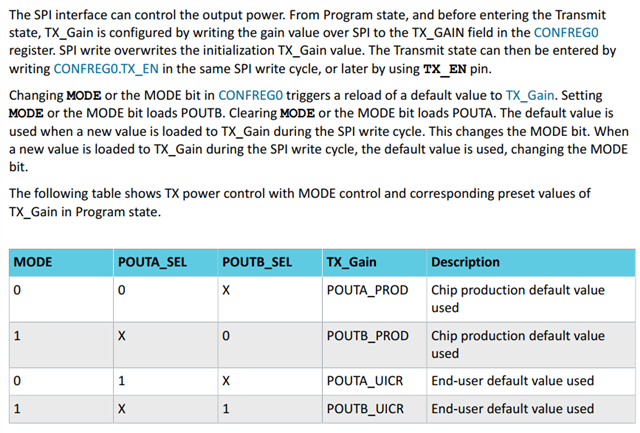
The nRF21540 RX gain is a fixed 13dB, it can not be configured in software. When using the nRF21540 with GPIO control the TX gain can be switched between 10 and 20dB using the MODE pin:
The two gain settings controlled by the MODE pin can be changed by writing to the CONFREG2 and CONFREG3 registers in the UICR:
Hi,
thanks for reply,
from datasheet I see.


Hi,
18day ago, no one reply?
Hi,
Sorry for not getting back to you sooner.
yoyou said:CONFREG0
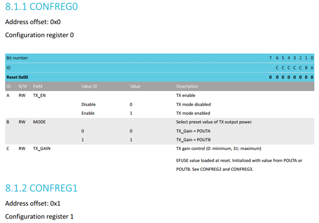
0x7D=1111101 (TX_GAIN=31, POUTA=20dB,TX=en)when GPIO MODE , no connect SPI to 21540,how to write CONFREG0 to max power?
To write to CONFREG0 the a SPI connection is needed. With GPIO only the register cant be written to.
yoyou said:pins:tx-en set logic high, enabledrx-en set logic low, disabledant-sel set logic low or connect to GND, use ANT1mode set logic low, POUTA=20dBabove is means (TX_GAIN=31, POUTA=20dB,TX=en,RX=disabed) ?
Yes, this pin configuration will give 20dBm output power in TX mode.
Best regards,
Bendik