Hi ,
can I connect nrf5340 pins D+and D- to the USB directly only via voltage translator from USB 5V to the nrf5340 1.8V main power?
Do you have a reference design for this purpose?

Hi ,
can I connect nrf5340 pins D+and D- to the USB directly only via voltage translator from USB 5V to the nrf5340 1.8V main power?
Do you have a reference design for this purpose?

Additionally, what is the minimum voltage level for the first programming? In the previous design with nRF52832, I encountered the problem when the initial programming voltage level was at least 2.5V. But power management circuit has started with 1.8V and only after uploading the FW might reconfigure the management circuit to 3V.
Hi Alex,
I am sorry but could you be a bit more clear on your first query? If it is whether the D+ and D- can be directly connected to 5V, then NO.

And you can also refer the VBUS detection specifications.
Further details are also available in the USBD documentation.
Best Regards,
Priyanka
Dear Priyanka,
Thank you for the reply.
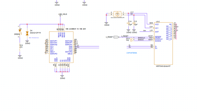
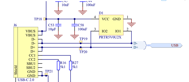
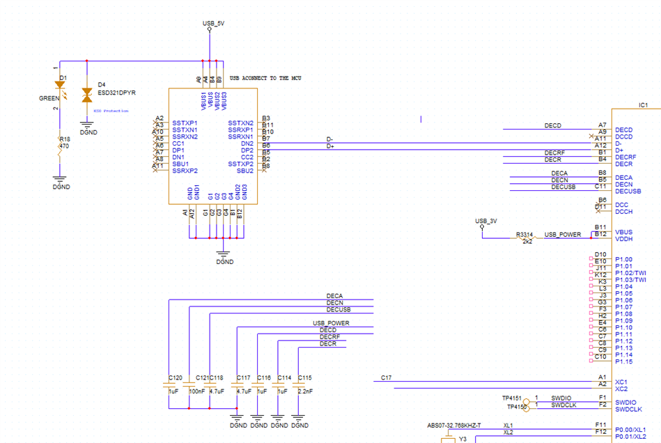
Refer to the schematic the USB is connected directly to the D+ D-.

But these pins are not tolerant to the 5v.
If I use some voltage translator between USB and D+ D-. pins will it work?
The links you sent aren't working.
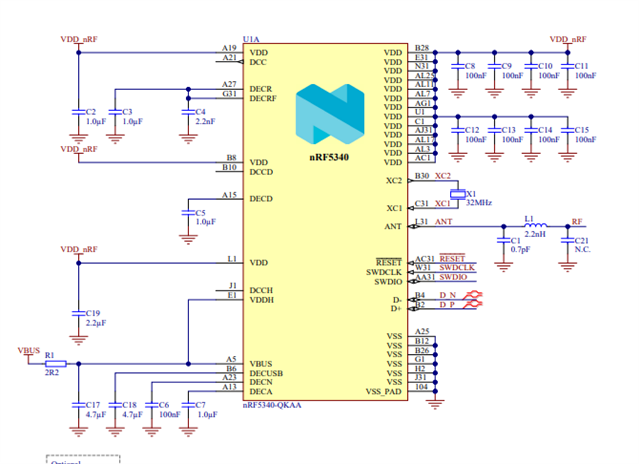
where can I find the reference UCB connection schematic?
Additionally, what is the minimum voltage level for the first programming? In the previous design with nRF52832, I encountered the problem when the initial programming voltage level was at least 2.5V. But power management circuit has started with 1.8V and only after uploading the FW might reconfigure the management circuit to 3V.
Dear Priyanka,
Thank you for the reply.
Refer to the schematic the USB is connected directly to the D+ D-.

But these pins are not tolerant to the 5v.
If I use some voltage translator between USB and D+ D-. pins will it work?
The links you sent aren't working.
where can I find the reference UCB connection schematic?
Additionally, what is the minimum voltage level for the first programming? In the previous design with nRF52832, I encountered the problem when the initial programming voltage level was at least 2.5V. But power management circuit has started with 1.8V and only after uploading the FW might reconfigure the management circuit to 3V.
Hi Alex,
I can share the links again. VBUS detection specifications and USBD documentation.
As for the D+ and D- pins, they can be connected to the USB, no need of changing the schematic, because they are 3V lines for USB and D+ is ESD protection.
As for the voltage level, at least a minimum of 1.7V should be supplied. You can take a look at the recommended operating conditions and the Regulator Control.
-Priyanka
hI
In case I understand it correctly I can connect D+ D- pins directly to the USB dedicated pins but connect B11&B12 power pins to the 3V .

Do I need to use a USB detection circuit or I can skip it without?
You need to connect 5V USB supply to the VBUS (B11 in your case). You can refer the recommended operating conditions.
But yes, you can connect VDDH and VBUS pins together according to the reference circuit design.
 '
'
You can read more about USB regulator support too.
-Priyanka
Do I need to use a USB detection circuit or I can skip it without?
No, you don't need an extra USB detection circuit as there is a detection event that is being triggered when you set 5V on the VBUS pin. A 4.7uF capacitor must also be added to the DECUSB pin in addition to VBUS and the data pins when using USB.