Hi,
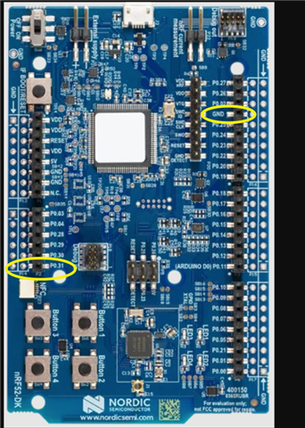
I am using an nrf52 DK and facing an issue regarding the GPIO voltage levels.
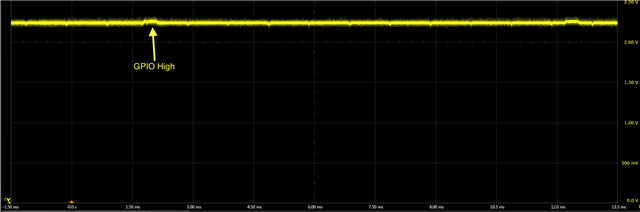
The GPIO voltage is around ~2.35V when its in LOW state and slightly increases when in HIGH state to around 2.40V.
The board was modified to enable current measurements as described in the online guide, and the GPIO pin is connected to an oscilloscope.
The code uploaded to the board looks as follows:
// gpio includes
#include "nrf_gpio.h"
#include "nrf_delay.h"
#define gpio 31


static void trigger_high(){
  nrf_gpio_pin_set(gpio);
}

static void trigger_low(){
  nrf_gpio_pin_clear(gpio);
}


int main(void)
{
    // ----------------- variables for matrix multiplication path -----------------------
    // num of rows and columns in each matrix
    int r1 = 4; int c1 = 4; int r2 = 4; int c2 = 4;
        int mat1[4][4] = {
            {1, 1, 1, 1},
            {2, 2, 2, 2},
            {3, 3, 3, 3},
            {4, 4, 4, 4}
    };

    int mat2[4][4] = {
            {1, 1, 1, 1},
            {2, 2, 2, 2},
            {3, 3, 3, 3},
            {4, 4, 4, 4}
    };
    int rslt[r1][c2];
    // ------------- end of variables for matrix multiplication path ---------------------


    nrf_gpio_cfg_output(gpio); //configure gpio pin as output

    while(true)
    {
      trigger_high();
      for (int repeats = 0 ; repeats < 80; repeats++)
      {
        for (int i = 0; i < r1; i++)
        {
            for (int j = 0; j < c2; j++)
            {
                rslt[i][j] = 0;

                for (int k = 0; k < r2; k++) {
                    rslt[i][j] += mat1[i][k] * mat2[k][j];
                }

            }
        }
      }
      trigger_low();
      nrf_delay_ms(10);
    }

}
And the GPIO voltage measurements looks like this on the oscilloscope:
Any idea about what might cause this voltage levels?