Beware that this post is related to an SDK in maintenance mode
More Info: Consider nRF Connect SDK for new designs

Accessing the nrf52820 pins

Hello all

I am porting the code from the nRF52DK to the nrf52820, and so far so good, however, I am having a question, when configuring the TWI, will this get me the right PINS, for instance, according to the module manufacturer I should be accessing the P0.02 for SDA, while P0.08 for the SCL , this is my code:

void twi_init (void)
{
    ret_code_t err_code;

    const nrf_drv_twi_config_t twi_config = {
       .scl                = NRF_GPIO_PIN_MAP(0, 8), // ARDUINO_SCL_PIN,   //Add you SCL Pin Here
       .sda                = NRF_GPIO_PIN_MAP(0, 2), // ARDUINO_SDA_PIN,   //Add you SDA Pin Here
       .frequency          = NRF_DRV_TWI_FREQ_100K,
       .interrupt_priority = APP_IRQ_PRIORITY_HIGH,
       .clear_bus_init     = false
    };

    err_code = nrf_drv_twi_init(&m_twi, &twi_config, twi_handler, NULL);
    APP_ERROR_CHECK(err_code);

    nrf_drv_twi_enable(&m_twi);
}

This part works on the nrf52dk, for example where I am directly using the P0.27 and P0.26, however, the numbers 26 and 27 are simply used, as 26 and 27... 

hence my question, if I am accessing the pins correctly?

best.

Parents
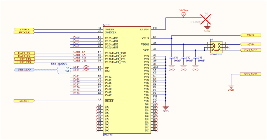
  • True that, I am looking at the el. schematics, ok, for example, how can someone enable or use the pin P0.20?

    for example, I have tried to toggle the P0.14 with the nrf_gpio_pin_write(14, 1); //P(0.14)   / nrf_gpio_pin_clear(14); the led, so, now I would like to do the same with the P0.20?

    Further more, I am trying to reach the pin F3, have a look at the attached pic, but not sure what M P stands for? 

    Was hopping that the GPIO could be assigned via software ...

    BEST. 

  • Hi and thank you for your input!

    I will try to answer your questions and elaborate what I had in mind.

    On page 10 you will see the pins identifiers C4 & C5 (not handy labels for software people ;-)

    Not sure what are you aiming here? btw SWDCLK, SWDIO , works ok, I can easily program the module. 

    I only do not see any official TWI (i2c) pins coming out of the microcontroller / PAN1781 module.

    I do not see it either, this is why I am looking at how to use the available GPIOs ... I think the GPIOs can be used for TWI...

    It tells you that it is impossble to use theese pins as a normal TWI pins?

    I am not trying to use the SWD..pins for the TWI...

    unclear what you want with the TWI on the pan1781 route to the swd pins?

    See above...

    2nd question  "I have tried to toggle the P0.14 ....   now I would like to do the same with the P0.20?"
    The the answer is simple 
    nrf_gpio_pin_write(12, 1); // to make the gpio  level high (assume positive signal level.)
    nrf_gpio_pin_write(12, 0); // to make the gpio  level low 

    Thank you for that, it makes sense! Slight smile

    The names are copied from the FT232R chip datasheet

    Thanks for that , will have a look...

    Thanks and the same!

    Best.

Reply
  • Hi and thank you for your input!

    I will try to answer your questions and elaborate what I had in mind.

    On page 10 you will see the pins identifiers C4 & C5 (not handy labels for software people ;-)

    Not sure what are you aiming here? btw SWDCLK, SWDIO , works ok, I can easily program the module. 

    I only do not see any official TWI (i2c) pins coming out of the microcontroller / PAN1781 module.

    I do not see it either, this is why I am looking at how to use the available GPIOs ... I think the GPIOs can be used for TWI...

    It tells you that it is impossble to use theese pins as a normal TWI pins?

    I am not trying to use the SWD..pins for the TWI...

    unclear what you want with the TWI on the pan1781 route to the swd pins?

    See above...

    2nd question  "I have tried to toggle the P0.14 ....   now I would like to do the same with the P0.20?"
    The the answer is simple 
    nrf_gpio_pin_write(12, 1); // to make the gpio  level high (assume positive signal level.)
    nrf_gpio_pin_write(12, 0); // to make the gpio  level low 

    Thank you for that, it makes sense! Slight smile

    The names are copied from the FT232R chip datasheet

    Thanks for that , will have a look...

    Thanks and the same!

    Best.

Children
No Data
Related