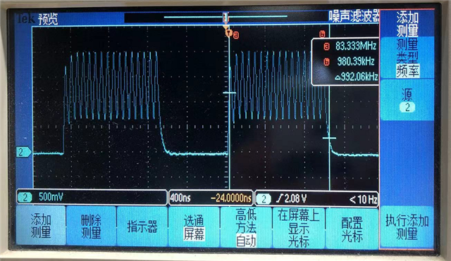
issue about QSPI SCK

Dear Nordic Engineers

I tested the QSPI example program. I encountered a problem would like to ask you.

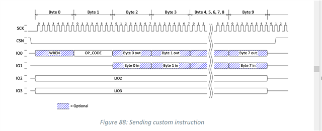
I use the logic analyzer to trace the SCK PINS, I would like to know the QSPI working's time series.  

 I use the logic analyzer connect to SB11 of NRF52840 DK and test QSPI example program.
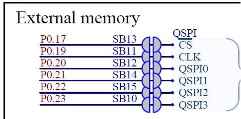
The following picture is the logic analyzer get SB11's waveform.

I read the NRF52840 Product Specification, the SCK looking is orderly and I think the clock pin should be like it. But I get the waveform of SCK pin looking does't have a rule.
Then I use the oscilloscope to get the waveform of SCK pin, I‘m more confused, the waveform isn't a square wave.
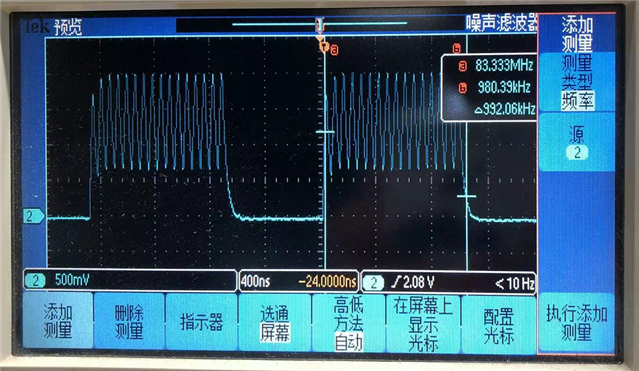
I tested the frequency of the small waveform, it's 16MHZ. But I look the QSPI code, it set QSPI frequency is 2MHz.
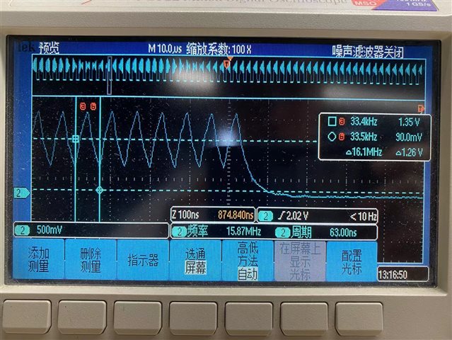
So I would like to know if this waveform is right?

Best ragards,

  • The following picture is the logic analyzer get SB11's waveform.

    It looks like you have setup to sample 5MHz, this is too slow to slow for QSPI in general, and for instance will make the clock signal to look with an inapproprioate duty cycle, but also in this specific case you likely will also miss clocks. I suggest to sample at for instance >50-100MHz.

    Then I use the oscilloscope to get the waveform of SCK pin, I‘m more confused, the waveform isn't a square wave.

    If you haven't already make sure to configure high drive (see NRF_GPIO->PIN_CNF[]) register on the pins used for QSPI, this should overall make nRF52840 be able to drive the pins better. Though have in mind that if you add probes on the QSPI pins, this will cause additional capacitance on the pins that may cause the issue you see here.

    Best regards,
    Kenneth

Related