

HI,
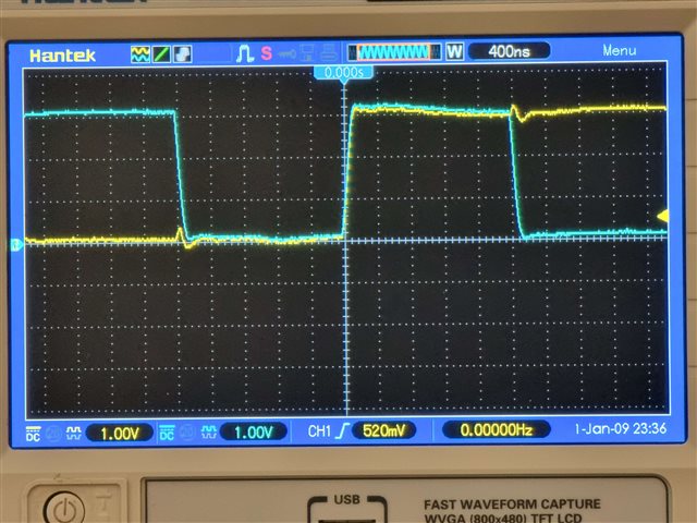
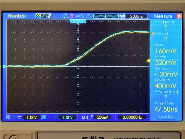
I'm trying to get an OLED display over SPI working but since I've no reaction yet, I probed the output and noticed it seems to have no write data hold time between MOSI and SCLK.
From Serial Peripheral Interface Master (SPIM) timing specifications, it's specified the write hold time to be more than 20ns and the display's IC datasheet says to be >40ns.
Here are the output with blue SCLK and yellow MOSI in SPI mode 2 (yep, not the best lines since it's not the shortest cables used for prototype :) )
And here the code used:
#include <nrfx_spim.h>
#include <string.h>

#define CS_PIN            40 /* P1.08 */
#define SCK_PIN           5 /* P0.05 */
#define DC_PIN            30 /* P0.30 */
#define MOSI_PIN          32 /* P1.0 */

#define SSD1333_DELAY_US  50

static void spim_init(uint32_t sck_pin, uint32_t mosi_pin, uint32_t cs_pin, uint32_t dc_pin) {
  nrf_spim_disable(NRF_SPIM3);
  k_usleep(SSD1333_DELAY_US);

  nrf_spim_pins_set(NRF_SPIM3, sck_pin, mosi_pin, NRF_SPIM_PIN_NOT_CONNECTED);
  nrf_spim_dcx_pin_set(NRF_SPIM3, dc_pin);
  nrf_spim_dcx_cnt_set(NRF_SPIM3, 1);
  nrf_spim_configure(NRF_SPIM3, NRF_SPIM_MODE_2, NRF_SPIM_BIT_ORDER_MSB_FIRST);
  nrf_spim_csn_configure(NRF_SPIM3, CS_PIN, NRF_SPIM_CSN_POL_LOW, 0);
  nrf_spim_frequency_set(NRF_SPIM3, NRF_SPIM_FREQ_250K);
  // nrf_spim_int_enable(NRF_SPIM3, NRF_SPIM_INT_ENDTX_MASK);
  nrf_spim_enable(NRF_SPIM3);
}

static void sendDisplayMsg(BYTE cmd, BYTE *data, size_t data_len) {
  BYTE *tx_buffer = k_malloc(data_len+1);

  tx_buffer[0] = cmd;

  if(data_len != 0 && data) {
    memcpy(tx_buffer+1, data, data_len);
  }

  nrf_spim_tx_buffer_set(NRF_SPIM3, tx_buffer, data_len+1);
  nrf_spim_rx_buffer_set(NRF_SPIM3, NULL, 0);
  k_free(tx_buffer);

  nrf_spim_task_trigger(NRF_SPIM3, NRF_SPIM_TASK_START);

  while(!nrf_spim_event_check(NRF_SPIM3, NRF_SPIM_EVENT_ENDTX)) {
    printk("Still tansmitting...\n");
    k_usleep(SSD1333_DELAY_US);
  }
  printk("END OF SPI TX.\n");
  nrf_spim_event_clear(NRF_SPIM3, NRF_SPIM_EVENT_ENDTX);
}

// sendDisplayMsg...
I didn't see any configuration option to act on the write hold time yet but I've some warnings about the board and don't know if it may interfere :
/Users/x/developpement/Quantum/build_1/zephyr/zephyr.dts:69.25-75.5: Warning (unique_unit_address_if_enabled): /soc/clock@40000000: duplicate unit-address (also used in node /soc/power@40000000)
/Users/x/developpement/Quantum/build_1/zephyr/zephyr.dts:345.21-349.5: Warning (unique_unit_address_if_enabled): /soc/acl@4001e000: duplicate unit-address (also used in node /soc/flash-controller@4001e000)
Is it expected behavior ?

