PDM on 5430 at 3.072MHz random glitches in the stream

Hi,

we have created a new product prototype where audio streaming is the functionality. 2 different HW revisions were so far built, the software originally is built to use a PDM to I2S converter chip, but now we had a chance to investigate the direct recording from the PDM microphones. The format we are using is 48Khz sampling 16bit stereo. This is working perfectly on I2S. However we have noticed weird behavior on the direct PDM recording. 

We managed to create the code to use the microphones, the limitations be:

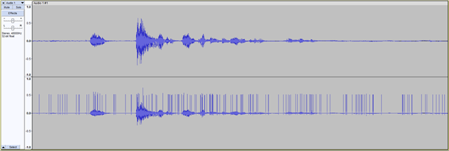
PDM clock is at 3.072 MHz (as 64X @ 48K) and ACLK clock source at 12.288 MHz. This yields the proper sampling speed. However it seems that the rising edge of the clock is glitchy at random intervals (we can't identify whether this  means 0 samples or some other bit errors, the glitch repeat at around 100ms intervals sounds like static clicking with varied amplitude). We have tested 3 boards and swapped the microphones from left to right to check that it is not the routing on the pcb or the microphones. Glitch stayed always on the rising clock edge. We even tried different IO voltages to rule that out as well 1.8V and 2.3V were tried.

Interestingly the falling edge sampling of the clock works perfectly. (we have muted the other channel to see).

What worked but not usable for us:

- change PDM clock source to 32MHz but this yields sampling rate of 50kHz
- change sampling rate to 24kHz -> this yielded 1.536MHz PDM clock and that ran again fine with the 12.288MHz ACLK source. 

So it seems that the glitch exists only on that one specific frequency (that we need of course). Our codec only allows 48/24/16/12/8 kHz sampling, so we can't try the 44.1kHz related frequencies.

Is there any known issues around this ACLK being 12.288MHz, and PDM clock at 3.072 MHz? Why does it only affect the rising clock edge? Is there anything we can do to make it work, or our best option is to go with the working speed of 24kHz audio sampling and 1.536MHz PDM clock?

Thank you 

Levente

Parents
  • Ohh one more thing, we have changed the PDM to I2S converter to output the same 3.072MHz (it was default to 32X), and the microphone streams over I2S still worked perfectly.

    Also we have tested grounding the PDM data pin while it was running and that caused silence on both channels no glitches heard.

    And we have changed the clock IO driving strength as well, on the scope the clock and data both looked pristine, very fast rising and falling edges on both.

  • Hi,

    I have asked internally and will get back to you as soon as I get a response.

    Best Regards,

    Priyanka

  • Hi @Priyanka, we have a lot more information to share. So we have adjusted the code to provide the PDM stream on USB audio so we can see the the "raw" samples, no compression. 

    Case 1. If the PDM is configured to use ACLK and 12.288MHz 48kHz sampling stereo 16 bit, the glitches occur, but we have also noticed the stream was indeed MONO. So only one side is sampled. Picture:

    The channels were identical before we normalized it, but lost that picture. (I mean besides the glitch).

    Case 2. Changed the sampling rate to 24KHz, 16bit stereo (we had to modify some usb descriptors, as those values seem to be hard coded in zephyr, but got it running nicely), then the recording had only one channel perfect, the other channel became an extreme noise with some correlation to the other channels audio. Clock source was again ACLK.

    Case 3. PDM sampling rate was dropped to 16kHz, Stereo, 16 bit, clock source to 32MHz Pclk, the result is perfect MONO 16kHz stereo 16bit stream (meaning that L-R are identical). Again, lost one whole channel. To make it worse as a next test we have enabled the L-R swapping, and still the same microphone was sampled, so that had no effect whatsoever. (even directly writing the PDM MODE register's EDGE bit, to be sure it changes).

    Case 4. Just to fuzz this a bit, we have tried to actually select mono channel, it did something, because the sample rate fell, but seems like the EDGE bit gets ignored still, because still always only one microphone was sampled (even though the documentation shows it should select which edge is considered LEFT so that L0 L1 samples could be changed from one-edge to the other).

    Now the question is, is there a working PDM example anywhere for the nrf5340 we could try on the hardware? (as stated above the HW works perfectly because if we enable the codec that is on the board. it is able to read both microphones fine and then we can ingest it over i2s, but the point is to try to get rid of the PDM to I2S converter). As far as we know your reference devkits all use codecs for the PDM, so we can't try those easily I guess. We have a BLE audio devkit, so if you could provide some code examples and wiring we could try to see if that works.

    - Levente

  • Hi,

    I have passed on the information to the experts. As for PDM support, hope this ticket helps.

    -Priyanka

  • Hi,

    There must have been a slight confusion or misunderstanding of maximum PDM_CLK frequency a customer would use on nRF5340, because of documentation issue on our end. 

    The understood spec when the PDM was first designed was to adhere to the values in the FREQ register

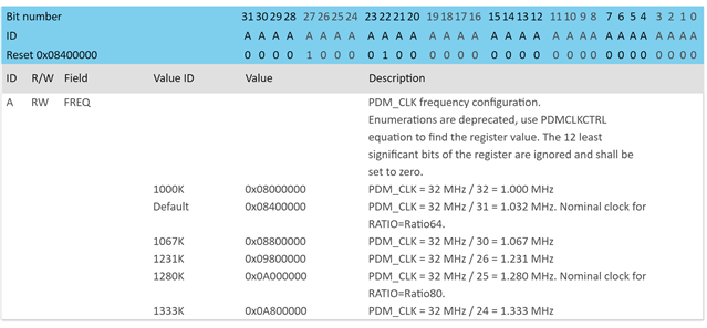
      So that was two combinations 1) 64 RATIO + 1.024 M (or 1.033 M if using PCLK). Then for nRF53 came the addition of the ACLK, and the FREQ or 2) RATIO 80 + 1.280 M FREQ configuration. 

    should have stated max frequency of PDM_CLK to be the typical ones (i.e. max 1.280 at ratio 80).

    Some thoughts shared by our experts:

    1) We have constrained the clocks to the filter at 4 MHz for both 52 and 53 series, so could that mess up anything in the filter when it is double PDM_CLK (i.e. 6 MHz?)

    - doesn't seem likely considering changing to PCLK resolved the problem.

    2) Is there an issue with path delay towards the IOs used at this frequency?

    Probably not, but have they observed the glitch at PDM_CLK IO with a scope or are they just assuming a glitch on rising edge because of the samples they listen to afterwards is bogus at 100ms intervals? Might be something with a sweet bad spot of path delay vs filter - covered in next point.

    3) Perhaps they could try using the different taps in the phase mux to shift the PDM_CLK at IO versus the PDM_CLK at the filter: https://projecttools.nordicsemi.no/infocenter/index.jsp?topic=%2Fyoda%2Fpdm.html&cp=3_3_0_0_6_25_7_29&anchor=register.PHASE

    4) It may be something with the "frequency doubler" design itself.
    Using the "frequency doubler" (enabled by default, and implemented to get closer to 1.024 M at the time we did not have the ACLK) the PDM_CLK is generated directly from the BaudRateGenerator, and the clocks towards the filter is generated on a posedge and negedge of that clock (so it's "double" of PDM_CLK (but it's not necessarily 50/50 duty cycle). They could try disabling it with https://projecttools.nordicsemi.no/infocenter/index.jsp?topic=%2Fyoda%2Fpdm.html&cp=3_3_0_0_6_25_7_18&anchor=register.FDBYPASS but then the BaudRateGenerator is creating the filter clocks directly, so the accumulator value must be double to get the same PDM_CLK frequency.

    That being said, I will keep you updated regarding any thoughts from the experts.

    -Priyanka

  • Thank you for the update! We'll keep monitoring this ticket. good to see that experts have some idea already. Let us know if there is anything we can do to verify a change if it can be done by changing the code.

  • Sure. I am currently awaiting a response from them, and will keep you posted. Slight smile

    -Priyanka

Reply Children
Related