NCS v2.0.0 - aws_iot sample - No UART output when using an overlay file

Hi,

I'm working with the NCS v2.0.0 - aws_iot sample and an nRF9160 on a custom board.

I have tested the aws_iot sample on an nRF9160DK and have confirmed that it works.

It appears that when I attempt to use an overlay file to change the TX and RX pins of UART_0, the UART output stops working.

I have tested this overlay file using hello world sample on my custom board and it outputs as expected.

I have attached my overlay file below, could you let me know what might be happening?

Thanks,

Alvin

6431.nrf9160dk_nrf9160_ns.overlay

Parents
  • If you look at GPIO interfaces and Virtual COM port you can see that P0.00 and P0.01 are connected to the Interface MCU. So when changing to these pins, the output should go out to another COM port when using P0.00 and P0.01.

    I tested this myself. First I connected the nRF9160 DK to the computer, and then I ran nrfjprog --com, and got the following output:

    $ nrfjprog --com
    960013235 COM37 VCOM1
    960013235 COM38 VCOM2
    960013235 COM39 VCOM0

    I then tried to program the hello_world sample to the nRF9160 DK, and the UART log was output on COM39. Then I applied your overlay file, and UART log was now output on COM38. See the below image.

    Do you see the same behaviour on your side? If not, could you upload your project here?

    Best regards,

    Simon

  • Hi Simon,

    I can confirm that using the overlay file with the hello_world sample works on my custom board. I was getting UART communication on P0.00 and P0.01.

    However when I attempt to use the same overlay file on the aws_iot sample, it no longer outputs anything on the UART.

    The aws_iot sample I'm using was found in the NCS v2.0.0 toolchain nrf > samples > nrf9160 > aws_iot

    Thanks,

    Alvin

  • Hi Simon,

    I was probing those pins you marked on the DK, however I just tested on my custom board which has a pinout attached directly to pin P0.01.

    When I run the at_client sample with the overlay file, I see UART TX on P0.01 and UART RX on P0.00.

    When I run the aws_iot sample with the overlay file, I don't see any activity on P0.01 and P0.00.

    Is there a reason I would see UART running the at_client sample and not the aws_iot sample while using the overlay file?

    Also, it seems like you were able to run your sample without adding those lines in the prj.conf file to enable SPM. Are we both running the same version of the SDK?

    Thanks,

    Alvin

  • Try to narrow down the issue

    One difference between aws_iot and at_client is that mcuboot is enabled. Try to disable that in aws_iot (CONFIG_BOOTLOADER_MCUBOOT=n) and see if that affects it somehow.

    Since you are able to see activity on P0.01 and P0.00 in hello world, could you try to remove part by part (except for printk, which should output on P0.00 and P0.01) from the aws_iot sample. Eventually you will end up with a clean main.c with only a main() function running printk. Using this approach you can figure out exactly what is causing the issue. If you still don't see anything with a clean main.c, try to remove configs from the prj.conf file. Remember to test regularly so you can pinpoint what is causing the issue..

    Best regards,

    Simon

  • With an empty main.c with just a printk():
    void main(void)
    {
        printk("The AWS IoT sample started, version: %s\n", CONFIG_APP_VERSION);
    }
     
    There is no UART output until I comment out the following lines in prj.conf:
     
    # MCUBOOT
    CONFIG_BOOTLOADER_MCUBOOT=y
    CONFIG_MCUBOOT_IMG_MANAGER=y

    # Image manager
    CONFIG_IMG_MANAGER=y
    CONFIG_FLASH=y
    CONFIG_IMG_ERASE_PROGRESSIVELY=y
    So it looks like it has to do with the MCUboot.
    I was able to get it to launch with the original contents of aws_iot main.c by going into the board file for nrf9160dk_nrf9160_ns (zephyr/boards/arm/nrf9160dk_nrf9160) and editing the nrf9160dk_nrf9160_common-pinctrl.dtsi file. I swapped the pin assignments for UART0 and UART1.
     
    uart1_default: uart1_default {
    group1 {
    psels = <NRF_PSEL(UART_TX, 0, 29)>,
    <NRF_PSEL(UART_RTS, 0, 27)>;
    };
    group2 {
    psels = <NRF_PSEL(UART_RX, 0, 28)>,
    <NRF_PSEL(UART_CTS, 0, 26)>;
    bias-pull-up;
    };
    };

    uart1_sleep: uart1_sleep {
    group1 {
    psels = <NRF_PSEL(UART_TX, 0, 29)>,
    <NRF_PSEL(UART_RX, 0, 28)>,
    <NRF_PSEL(UART_RTS, 0, 27)>,
    <NRF_PSEL(UART_CTS, 0, 26)>;
    low-power-enable;
    };
    };

    uart0_default: uart0_default {
    group1 {
    psels = <NRF_PSEL(UART_TX, 0, 1)>,
    <NRF_PSEL(UART_RTS, 0, 14)>;
    };
    group2 {
    psels = <NRF_PSEL(UART_RX, 0, 0)>,
    <NRF_PSEL(UART_CTS, 0, 15)>;
    bias-pull-up;
    };
    };

    uart0_sleep: uart0_sleep {
    group1 {
    psels = <NRF_PSEL(UART_TX, 0, 1)>,
    <NRF_PSEL(UART_RX, 0, 0)>,
    <NRF_PSEL(UART_RTS, 0, 14)>,
    <NRF_PSEL(UART_CTS, 0, 15)>;
    low-power-enable;
    };
    };
    You mentioned above that the overlay file added doesn't affect MCUboot. Is there an overlay file I can add to the project to assign the pins for MCUboot without editing the board file directly?
  • alvin.le said:
    You mentioned above that the overlay file added doesn't affect MCUboot. Is there an overlay file I can add to the project to assign the pins for MCUboot without editing the board file directly?

    You can do this using the following approach: my_app/child_image/mcuboot/boards/nrf9160dk_nrf9160.overlay (The mcuboot is built as secure, so don't use the 91 ns board selection).

    For more information see Multi-image builds → Image-specific variables

  • It looks like that worked, thanks Simon. However, it looks like mcuboot defaults to using TF-M instead of SPM now using this method.

    Is there something that I can change to make TF-M work for this example?

    When I try to add a mcuboot.conf file to the my_app/child_image/mcuboot/ folder to use SPM instead of TF-M, I get the following error:

    --------

    mcuboot.conf:

    # SPM
    CONFIG_SPM=y
    CONFIG_BUILD_WITH_TFM=n
    -------
    Error message:

    firmware-m/Kconfig:104, Kconfig.zephyr:632) was assigned the value 'y' but got the value 'n'. Check
    these unsatisfied dependencies: (BUILD_WITH_TFM || !MCUBOOT) (=n). See
    docs.zephyrproject.org/.../kconfig.html and/or look up
    BOOTLOADER_MCUBOOT in the menuconfig/guiconfig interface. The Application Development Primer,
    Setting Configuration Values, and Kconfig - Tips and Best Practices sections of the manual might be
    helpful too.

Reply
  • It looks like that worked, thanks Simon. However, it looks like mcuboot defaults to using TF-M instead of SPM now using this method.

    Is there something that I can change to make TF-M work for this example?

    When I try to add a mcuboot.conf file to the my_app/child_image/mcuboot/ folder to use SPM instead of TF-M, I get the following error:

    --------

    mcuboot.conf:

    # SPM
    CONFIG_SPM=y
    CONFIG_BUILD_WITH_TFM=n
    -------
    Error message:

    firmware-m/Kconfig:104, Kconfig.zephyr:632) was assigned the value 'y' but got the value 'n'. Check
    these unsatisfied dependencies: (BUILD_WITH_TFM || !MCUBOOT) (=n). See
    docs.zephyrproject.org/.../kconfig.html and/or look up
    BOOTLOADER_MCUBOOT in the menuconfig/guiconfig interface. The Application Development Primer,
    Setting Configuration Values, and Kconfig - Tips and Best Practices sections of the manual might be
    helpful too.

Children
  • alvin.le said:
    However, it looks like mcuboot defaults to using TF-M instead of SPM now using this method.

    What do you mean by "this method"? Do you mean that after adding an overlay file my_app/child_image/mcuboot/boards/nrf9160dk_nrf9160.overlay, TF-M us used instead of SPM?

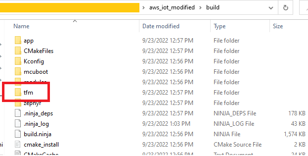
    When I build the aws_iot sample with NCS v2.0.0 without any mcuboot overlay file the TF-M is used (see below image). So I don't think adding an mcuboot overlay file should make a difference.

    Also what do you mean by "mcuboot defaults to using TF-M"? It is the application (aws_iot) that decides whether TF-M or SPM should be used. MCUboot, TF-M and SPM are all child images of the application, and it is the application that decides what child images should be used or not.

    alvin.le said:

    When I try to add a mcuboot.conf file to the my_app/child_image/mcuboot/ folder to use SPM instead of TF-M, I get the following error:

    --------

    mcuboot.conf:

    # SPM
    CONFIG_SPM=y
    CONFIG_BUILD_WITH_TFM=n
    -------

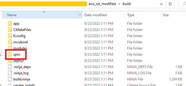
    If your goal is to make the aws_iot sample use SPM instead of TFM, you should modify aws_iot/prj.conf instead. I added CONFIG_BUILD_WITH_TFM=n and CONFIG_SPM=y to aws_iot/prj.conf and the program built and ran without any issues, and you can see in the image below that SPM is used:

    Best regards,

    Simon

  • It looks like I incorrectly assumed that the output below occurs when TF-M is used as opposed to SPM because the SPM folder shows up in the build like your image above, so that's not the issue.

    It looks like what I needed to do was take that overlay file and place it in a folder for SPM in the child_image folder. my_app/child_image/spm/boards/nrf9160dk_nrf9160.overlay.

    That seems to do the trick and I'm able to get to the contents of main.c now.

    I'm still not certain why the assignment of the UART pins hangs up the application.

    Thank you for your help on this Simon, I appreciate it.

Related