Operate nRF52840 PDK version 0.9.0 at 1.8V VDD while debugging

Hello,

I would like to use the nRF52840 PDK version 0.9.0 at 1.8V VDD since my peripherals operate at 1.8V. At the same time, I would like to debug the DK through USB.

I followed the corresponding section in the manual and completed these steps:

  • 1.8V external voltage connected to P21
  • VEXT->nRF switch is in the ON position
  • USB connected on J2
  • SW9 on VDD
  • SW6 on default

Nevertheless, I still measure a VDD voltage of 3V at P1.

While searching for an explanation, I noticed a difference in the schematics between DK version 0.9.0 (which I use) and the more recent versions. 

In version 0.9.0, VDD_nRF_SENSE is not connected to SW10.
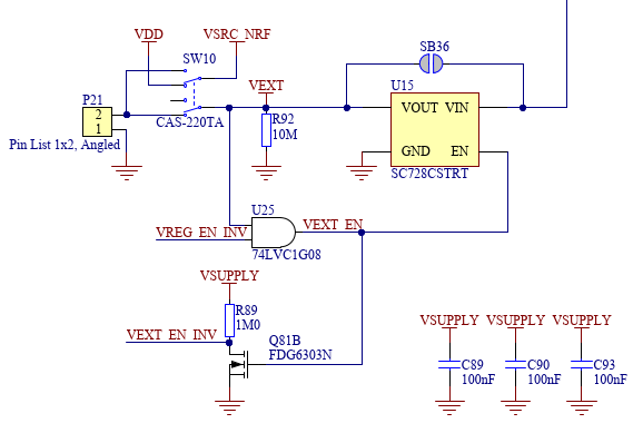
In the more recent versions, VDD_nRF_SENSE is connected to SW10.
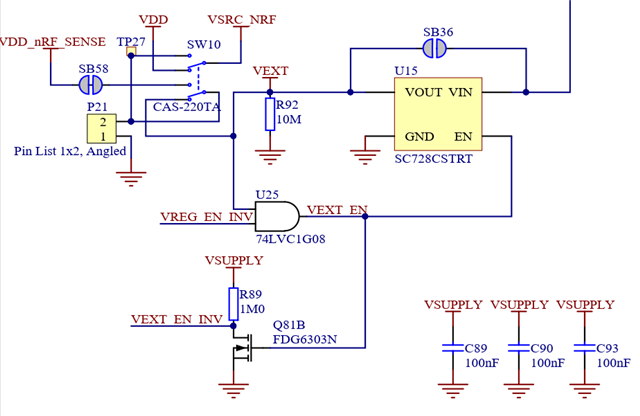
Could this be the reason that the VDD voltage stays at 3V instead of going to 1.8V as expected?

Thank you for the help,

Sebastian

  • Hi there,

    The correct approach would be to modify the REGOUT0 register in the UICR so that it's set to 1V8. It should be this by default, unless you have modified it already. Can you read out the REGOUT register from the UICR with nRF Command Line Tools?

    EDIT: This will actually have no effect when supplying through the J2 USB header, see my newest reply.

    nrfjprog --memrd 0x10001304

    regards

    Jared

  • Hi Jared, thank you for the answer.

    Here's the readout of the register:

    nrfjprog --memrd 0x10001304
    0x10001304: FFFFFFFF |....|

    So, if I understand correctly, the voltage should already be set to 1.8V.

  • Hi Jared,

    Is there anything else that I could try to get the VDD to 1.8 V?
    The REGOUT0 register seems to have no effect.

  • Hi there,

    I'm sorry but I have to retract my previous answer. Changing the REGOUT0 register will actually have no effect on the onboard VDD when supplying from the J2 header. 

    The VDD domain of the nRF chip is "VDD_nRF", while the VDD of the board is called just "VDD", VDD  powers the LEDS, interface chip etc, and will always be 3V when powered from the J2 port. When you adjust the REGOUT0 register you're actually configuring VDD_nRF, and this is only when the board is supplied from the J3 nRF_USB port. VDD_nRF can be measured from the P20 header and supplied on the P21 port. 

    The problem is that VDD and VDD_nRF is connected together by default, VDD will therefore pull VDD_nRF up if it's lower. For example when the board is supplied from the J2 header, VDD will be 3V, if VDD_nRF is lower then it will be pulled up to 3V as well. If you want to set the VDD_nRF to 1V8 then you have to disconnect the nRF chip from rest of the board by setting SW6 to nRF_only. You can then power VDD_nRF directly from the P21 external supply port.

    Could this be the reason that the VDD voltage stays at 3V instead of going to 1.8V as expected?

    VDD_nRF_SENSE is used by the onboard high voltage regulator. It's used when SW9 is set to either "USB" or "LiPo", and the board is supplied from the either the LiPo or nRF_USB port. VDD__nRF SENSE makes sure that VDD is equal to VDD_nRF. 

    regards
    Jared 

  • Thank you very much for the detailed answer!

    I am able to power the nRF through P21 with 1.8V, and indeed VDD_nRF is 1.8V.

    My problem however is, that when I power the nRF externally, I am no longer able to program/debug the nRF through the J2 USB connector. Is is simply not possible to power the nRF externally with 1.8V and to debug through J2 at the same time? Or is the a possible solution for this?

    If it's not possible, I assume I have to switch to an external debugger connected at P18?

    regards,

    Sebastian

Related