AoA IQ Data soundness

Hi, I'm currently using the Direction Finding Connectionless examples to evaluate using the nRF5340 for numerous projects we have lined up, and I'm having difficulty ascertaining whether or not I'm actually collecting valuable data.

I've made minimal changes to the example, just set up the GPIO overlay to match the antenna array we are using and setting up a very basic switching sequence.

My overlay file is currently set to use 3 antenna, with 0x3 set as the reference antenna.

	dfe-antenna-num = <3>;
	dfe-pdu-antenna = <0x3>;

My switching sequence is then set to {0x5,0x9}.

My understanding then is that of the 45 samples I receive from the CTE, the first 8 would be using ANT 0x3, allowing me to ascertain a reference phase using arctan2(Q,I), then the remaining would alternate between ANT0x5 and ANT0x9. From the switching samples I calculate a phase offset and use the basic θ = arccos((ψλ)/(2πd)) formula to calculate an angle.

My first 2 most basic questions are so:

1. Obviously, this approach is going to struggle with noise and reflections etc, but I'm unsure as to how big those effects might be - how flakey I should expect this naive appraoch to be. 

2.  The IQ samples themselves, I'm unsure as to what range of values I should be expecting. In most of my testing so far the majority of my samples are in the range 0±50, which from looking around on this site seems to be low.

I'm reasonably confident the data I've collected so far is garbage, and will have more equipment available soon to properly interogate my hardware setup (WFH introduces some unfortunate delays at times), but I want to check it's not my analysis of the data that's the issue.

When calculating the reference phase, I use atan(Q,I) and see that odd samples are consistently ~180° out of phase with even samples. Is this expected behaviour, and if not how am supposed to ascertain the reference phase, are there supposed to be two reference phases for odd an even sample slots? My intuition is no but as I'm sure is obvious, I'm very much learning on the job here.

Parents
  • Hi

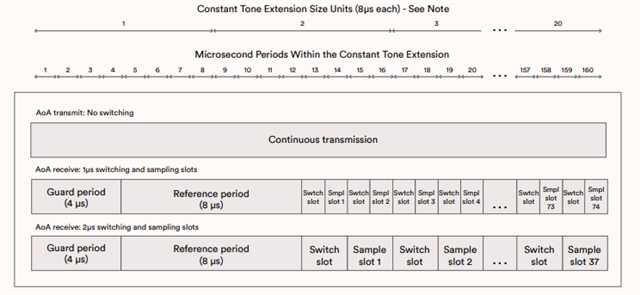
    From the Direction Finding technical overview from Bluetooth, you can see that the Guard and Reference period is done first, then you do switching between antennas and sampling. Here you need to switch between all (3 in your case) antennas until the sampling period is over.

    Guard periods, used in many communications systems, are a technique designed to ensure there’s a gap between adjacent transmissions so that they do not interfere with each other.

    During the reference period, 8 x IQ samples are acquired from the first antenna at 1µs intervals. No antenna switching occurs during the reference period. The host may be able to use the 8 reference samples to estimate the frequency of the signal and, from this, the wavelength. This allows more accurate angle calculations to be performed.

    Sample and switch slots may either be 1µs or 2µs long. Support for 2µs slots is mandatory while support for 1µs is optional. HCI configuration indicates which slot length is to be used by the controller.

    The full technical overview can be downloaded here.

    Best regards,

    Simon

Reply
  • Hi

    From the Direction Finding technical overview from Bluetooth, you can see that the Guard and Reference period is done first, then you do switching between antennas and sampling. Here you need to switch between all (3 in your case) antennas until the sampling period is over.

    Guard periods, used in many communications systems, are a technique designed to ensure there’s a gap between adjacent transmissions so that they do not interfere with each other.

    During the reference period, 8 x IQ samples are acquired from the first antenna at 1µs intervals. No antenna switching occurs during the reference period. The host may be able to use the 8 reference samples to estimate the frequency of the signal and, from this, the wavelength. This allows more accurate angle calculations to be performed.

    Sample and switch slots may either be 1µs or 2µs long. Support for 2µs slots is mandatory while support for 1µs is optional. HCI configuration indicates which slot length is to be used by the controller.

    The full technical overview can be downloaded here.

    Best regards,

    Simon

Children
No Data
Related