NRF_GPIOTE EVENTS_PORT woes (again)

I have my own code for handling pin interrupts using the NRF_GPIOTE EVENTS_PORT interrupt. I had some issues with this years ago when I was using the nRF52832 chip, which only has one port. The nRF52833 has two ports and I have interrupts on pins in both ports. I've discovered a new problem that seems kind of an inherent flaw with the hardware design.

I've always thought it was a strange system. All input pins are routed through one DETECT signal that, on the rising edge, triggers the EVENTS_PORTS signal that generates the interrupt. The problem is that the DETECT signal can only be brought low by scanning each input pin state inside the interrupt and reconfiguring the SENSE of each pin that would cause it to appear triggered in the LATCH register. After each pass through, you have to check the LATCH register to see if all of the input pins are now in the correct SENSE. If not then you have to keep scanning the pins until you can get all bits in the LATCH register cleared. Only then can the DETECT signal be brought low so that it can transition from low to high to generate another EVENTS_PORT signal. Because of this scheme, you have to always interrupt on both edges of every input and only handle the state that you want.

It's very important to understand that the DETECT signal cannot be queried directly. It can only be queried indirectly via the LATCH register!

As cumbersome as this is, it was at least possible to implement it with the nRF52832. With the nRF52833, having two ports, it appears that this scheme is impossible to implement because there are now two LATCH registers feeding into the one DETECT signal. That means there is no atomic instruction for determining if all latch bits have been cleared. And with no access to the DETECT signal, there is no way to know if both LATCH registers are clear simultaneously.

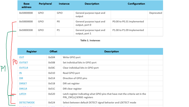
In fact, it looks like there is a flaw in the documentation. Figure 1 of the GPIO documentation for the nRF52833 shows the same block diagram for the nRF52832, but it isn't really the same. There should be two LATCH registers and two DETECTMODE registers; one per port. I assume the two LATCH registers go through an OR gate to the DETECT signal. In that case, there is no way to determine if the DETECT signal has actually been brought low, so as to re-enable the interrupt generation.

My conclusion is that one cannot safely use both ports for interrupts; only one or the other. Please, someone convince me I'm wrong. This is a significant problem for my application.

  • Hello,

    I am not sure if I fully understand the problem, if you in the gpiote interrupt handler find that the EVENT_PORT has occured (and clear it) and then check the LATCH register(s) (and clear those set), this may iterate a few times depending whether new EVENT_PORT/LATCH are triggered during gpiote handler execution as you write, however if there are new source(s) for the DETECT signal triggering the EVENT_PORT, after EVENT_PORT was cleared, would then not the gpiote interrupt be fired again immediately after such that those also can be handled? 

    Looking at the nrfx_gpiote_irq_handler() and port_event_handler() implementation in nrfx_gpiote.c I don't quite understand where the race condition you are afraid of occurs:
    https://github.com/NordicSemiconductor/nrfx/blob/master/drivers/src/nrfx_gpiote.c#L1316 
    https://github.com/NordicSemiconductor/nrfx/blob/master/drivers/src/nrfx_gpiote.c#L1157 

    If you are the nRF5 SDK you may need to look at this file instead:
    https://github.com/NordicSemiconductor/nrfx/blob/nrfx-1.x/master/drivers/src/nrfx_gpiote.c 

    Edit: I might be able to see a problem if you have fast toggling input signal (e.g. >1kHz range), but in that case maybe using IN event is a better suggestion than PORT_EVENT for those pins in specific.

    Kenneth

  • Kenneth, Thanks for chiming in. I'm hoping a new perspective will help me set this aside.

    1) The documentation is wrong, as I indicated. There are two LATCH registers and two DETECTMODE registers. The 52833 documentation should be updated, accordingly, so that we can see how the hardware really works.

    2) The GPIOTE documentation says "The event will be generated on the rising edge of the DETECT signal.". That means the DETECT signal must be brought low before there can be a (subsequent) rising edge. Simply setting the EVENTS_PORT register to 0 will not cause another interrupt. 

    3) The race condition stems from the fact that you have to read two different (LATCH) registers to detect the bits that need to be cleared because there is no way to read the DETECT signal. (It would be nice if there was a secret register somewhere that would allow it.) Since these bits are set in hardware, the setting of them cannot be disabled while reading the registers. That means while reading P0->LATCH, bits in P1->LATCH can be set and vice versa. This is really the crux of the problem. Typically, if you run into a situation like this, you create a critical region around your non-atomic reads. In this case, you can't. There doesn't appear to be a way to stop the hardware from updating the LATCH registers.

    4) I installed a workaround by looking at the LATCH registers in my main (non-interrupt) loop. Sometimes I see a bit set in a LATCH register. (To be clear, this should never happen because an interrupt should be generated before my main context code has a chance to read it.) Upon detection, I set the LATCH bits back to 0 and that keeps the system going, although I obviously lost an interrupt in the process.

  • Let me check internally and get back to you (this will take several days).

    Kenneth

  • Hello again, 

    I have done some digging here.

    I see your point about the documentation seems wrong, but the GPIO chapter do describe each port individually, so it do seem fine if you look at it this way (I do however have some additional information about how the DETECT signal is "joined" from each port to the GPIOTE module at the end here):

    But to answer your most pressing problem about GPIO_EVENT, DETECT and SENSE I want to refer to the following chapter:
    https://infocenter.nordicsemi.com/topic/ps_nrf52833/gpio.html#concept_o12_bgv_bs 

    "The LDETECT signal will be set high when one or more bits in the LATCH register are 1. The LDETECT signal will be set low when all bits in the LATCH register are successfully cleared to 0.

    If one or more bits in the LATCH register are 1 after the CPU has performed a clear operation on the LATCH register, a rising edge will be generated on the LDETECT signal. This is illustrated in DETECT signal behavior."

    With DETECTMODE=LDETECT, the DETECT signal comes from LATCH instead of directly from pins, and if you clear LATCH, it automatically pulls the DETECT low in order to generate a new edge. It's important that you use LDETECT in this case, because I have received confirmation from one of the designers that the DETECT signal is gated by LATCH clearing *after* OR'ing all port+pin contributions (but only when DETECTMODE=LDETECT.) The "masking" of the LATCH clearing occurs for 16 clock cycles. 

    Based on the above I do believe the implementation now is safe to always trigger the Port event by using LDETECT, ref: "PORT is an event that can be generated from multiple input pins using the GPIO DETECT signal. The event will be generated on the rising edge of the DETECT signal."

    Best regards,
    Kenneth

  • That link doesn't work for me and I haven't been able to do a web search that leads me to that text you quoted. I'm looking at the Nordic Infocenter documentation for nRF52 Series:nRF25833:GPIO.

    I agree that the ambiguity is related to how the two GPIO:DETECT signals are joined to trigger the one GPIOTE:EVENTS_PORT, which is why I think it would be very helpful to have both a logic and timing diagram. In that sense, GPIO:Figure 1 isn't "wrong", just incomplete.

    At the start of your reply, there is an implication that there are two DETECT signals; on per port. At the end, you quote the GPIOTE text, which sounds like there is only one DETECT signal.

    The problem is that one ISR has to service interrupts for two ports. This is different from other peripherals (e.g. I2c), where each instance has its own interrupt handler. So if P0->LATCH has a bit set and P1->LATCH has a bit set then both have to be cleared in the one ISR. In this scenario, if I clear the bit in P0->LATCH will a new event be generated, even though I haven't cleared P1->LATCH, yet? If so, that means my ISR is going to be re-entered before I service the P1 bits. If not, then there's a race condition getting both LATCH registers clear. Both seem fraught with peril. But knowing which is correct would be helpful.

    All of this seemed perfectly clear when there is one port, but maddeningly unclear when there are two. Pictures are nice. Slight smile

Related