TWIM driver issue with LSM6DS3TC-R

Hi,

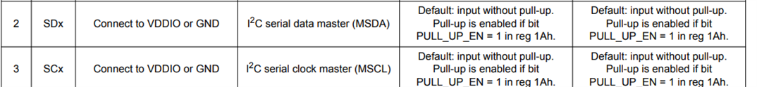
I need to read out the Gyro Data of an LSM6DS3TC-R via I2C/TWI. The xiao nrf board uses an nrf52840 and has the gyro sensor build into it, so I don't have access to the pins with an oscilloscope. I know the connection as it is drawn in the schematic I attached is working, because with the original bootloader by xiao with their own i2c library it is working fine.

There is a little problem I want to point out first: The TWIM driver returns immediately with NRF_SUCCESS when starting a transfer with nrfx_twim_xfer() with the NRFX_TWIM_FLAG_NO_XFER_EVT_HANDLER flag enabled. I don't know if that is intended or not, but for me it seems more reasonable to not use the event handler with that flag set, even though during initialisation an event handler was specified.

Now the second problem: When trying to initialise the sensor by reading out the so called "WHO_AM_I" register, sometimes the TWIM driver hangs itself in the nrfx_twim_xfer() function because no event is being set, after the TXSTARTED event. When debugging after the program is stuck in that loop of event checks, lines 538, 544 and 551 of nrfx_twim.c file. I did not manage to reproduce that error in a certain way, sometimes it occurs, sometimes it doesn't and the sensor is working fine, with exactly the same code.

I already tried using the nrfx_twi driver instead or even the nrf_drv_twi but the results were similar. The twi_scanner example sometimes works and sometimes doesn't work, as it hangs itself in the same part of the code. I also tried manually resetting the i2c bus with the nrf_twim_twi_bus_recover function before initialising the twi driver, but that also doen't change anything. I also tried to clone the xiao "Wire_nRF52" lib from the original bootloader but even that resulted in the same problems.

The pins used internally for the Sensor are P0.07/SDA and P0.27/SCL and P0.07 is also used for TRACECLK, is that maybe the problem? Because the only difference there is anymore, is that the original bootloader uses no debugging via the J-Link, but has dfu enabled for the Arduino IDE.

The code I wrote is quite much by now, but if it helps, I could also post it.

I am using: Segger Embedded Studio v5.42a, nRF SDK 17.1.0, Softdevice S212 7.1.0 on an XIAO nRF52840 BLE Sense with a J-Link to flash via SWD.

I am thankful for every answer that could help... Thanks in advance!

Parents
  • It is a bit difficult to say what is wrong, but the loop in which it is stuck seems to say that the transfer was initiated and none of the events occurred in the hardware. Without oscilloscope data we can only guess few things.

    1. If you suspect if it has something to do with NRFX_TWIM_FLAG_NO_XFER_EVT_HANDLER enabled, then disable it and give the proper event handler just for testing.
    2. Try to debug this with logs/prints and not using TRACECLK if you suspect this could be issue. If the program behaves differently in debug mode and in normal mode, then it is likely that it has to do with shared pins with debug interface.

  • Hi,

    yes, the problem definitely is that of the three TWIM events that are checked occurs. I already tried it without the no event handler flag, and also in debug vs release mode - no difference in behaviour. I even tried to check the ERRORSRC Register in the twim driver as well, but neither the ANACK nor the DNACK bit is set. Also Logging basically everything shows the same result.

    I am not using the TRACE lines - even checked the nrf.h file for the project in SES, but everything seems to be initialised (deactivated) correctly.

    The problem with oscilloscope data is, that the gyro sensor is not accessible on the xiao board. I thought of routing the gpios to other ones via PPI, to simply mirror the SCL and SDA lines to other pins that are accessible with the oscilloscope. Could that work or does the SDK/hardware not allow such functionality?

    Best regards!

  • Hi,

    I just added the config of the ppi peripheral to mirror the i2c lines to accessible pins on the breakout boards, which works as it should: Blue=SCK Red=SDA Green=Power of the LSM6DS3. The next image shows the lines when the sensor is working:

    Working I2C lines

    Now if I just unpower and power the board back on, nothing happens on SCK and SDA lines :

    Power on after TWI init

    I even tried "power cycling" the gyro sensor by turning the 6D_PWR line in the schematic on and off like this:

    Power cycling EN line

    but the data and clock line remain low, as if the sensor would pull them low, even though it isn't powered...

    Regards, Fabian

  • I am not familiar with this sensor but looking at its data sheet it seems like it is possible to configure the sensor to control the pull of the SDA and SCK pins.

    There are three things

    1. Pull configuration from the master side of the actual SDA/SCK pins that are connected to the sensor.
    2. Pull configuration from the sensor side of the actual SDA/SCK pins that are connected to the sensor.
    3. pull configuration of the fork pins you are using that are connected to the oscilloscope. Maybe at powerup the ppi/gpiote configuration you made to simulate a fork of the sda/sck pins have a bug?

    I suspect that what you are seeing might be something else than what is going on the actual pins. I would recommend you to set the gpio state of the forked (SDA/SCK) pins to a known state at startup before connecting those fork pins to the PPI/GPIOTE combo. If you do that then we can atleast exclude point number 3. 

  • I2C requires pull-ups on both SDA & SCL.  The board does not have those resistors therefore you must enable it in the driver.  

  • It has two 10k Pulup resistors. They are drawn in the middle of the same page as the gyro sensor in the schematic...

  • Sorry I didn't see it.  There is something else however.  The LSM6DS3 is powered by a gpis pin 1.08.  Have you enable it ? Configure it as output and set it to high ?

Reply Children
No Data
Related