Problems with: Programming custom board with nRF5340 MCU by nRF5340 DK via P20 and nRF Connect for VS Code

Hello, I have a custom board with nRF5340 MCU. I'm a hardware engineer and we have firmware engineers for programming it.

Trying to connect and erase/reboot my custom board through nRF5340 DK with VS Code and nRF Connect says: Error resetting device. See the Output tabs for more details.

Problems:

Output tab is always emtpy. What should I see there?

Why I can't connect to my custom board? Our programmers can easily connect to our boards with J-Link Segger.

My board's VDD is 1.8V.

I connet P20.2 with P20.3 so VTG and VDD nRF' are connected.

P20.4 (SWD IO) goes to SWDIO on my board.

P20.5 (SWD CLK) goes to SWD CLK on my board.

P20.7 (RESET) goes to nRESET on my board.

P20.12 (VIO REF) goes to VDD on my board to detect my VDD and make its own VDD the same (1.8V)

I press erase/restart in VS Code and get error that is described above. I can even see that on my test points of my boards on SWD CLK and IO there are some activity with right voltage level (1.8V). But my target MCU is not answering. What can be a problem? J-Link Seger works well.

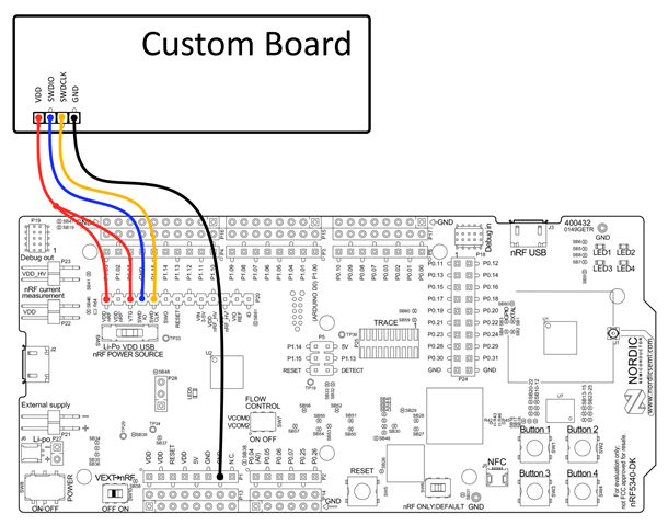
  • Yea, so there seem to have been a error in our labeling of the pin label GND DETECT, it should be N.C. This will be fixed(re-labeled) in a on newer version of the DK.

    But made a diagram for you to use, when using P20 as the programmer interface.

    VDD_nRF and VTG should be joined so that the programmer know that there is power on the external/custom board. Then only SWDIO, SWDCLK and GND is needed to program a external device from P20.


     Regards,
    Jonathan

  • I don't understand why, but there's no more button Reply under your answerings. Ok. Replying here.
    Your suggestet connection will burn my MCU because you didn't mentioned

    1. VIO REF. Without it all the signals will be 3V. And my board is 1.8V, as I already mentioned in my issue explanation.

    2. As I already mentioned "I connet P20.2 with P20.3 so VTG and VDD nRF' are connected." So programmer understands that it needs to program not its onboard chip but some other target on P20. And I even see some activity on SWD IO / CLK pins on my board, and they are even have 1.8V, right, voltage. But it's not progamming.

    P19 is ok and I see the same activity. Why I say activity is because CLK looks like SWCLK in both options (P19/P20), SWDIO looks like there is some data, I just don't parse it, it's very long and I can't compare those trases.

  • Sorry about the reply button issues, this can happen sometimes, often refreshing the page a couple of times or click on the date\time under a users name.

    The buttons should then show up again.

    elektron314 said:
    connection will burn my MCU

    Do you have other components that can not exceed 1.8V ? The nRF53 should have no issues being programed at 3V.


    Have you modified P19 to use external supply ?
    Adding link to the debug out section : https://infocenter.nordicsemi.com/topic/ug_nrf5340_dk/UG/dk/hw_debug_out.html?cp=3_0_4_3_9

    And just to be sure, you don't have something connected to P19 and P20 simultaneously, P19 is default int that case.


    Regards,
    Jonathan

  • What do you mean by modifying P19?

    No, and I didn't connect anything else simultaneously as you epxlained.

    Everything I did is described above. I don't have nothing to add more.

  • elektron314 said:
    What do you mean by modifying P19?

    Its possible to short solder bridge SB47, that's what i was referring to, sorry for not being clearer.

    You mention that "J-Link Seger works well" in your original post. What do you mean by this?

    You can use the nrfjprog tool and add --log to enable logging, this will make a log.log file that we can look at.

    Regards,
    Jonathan

Related