Request for information regarding the matching network in the schematic of NRF9160 DevKit

Hello all!!! 
I am new to the field of antennas and have lately been struggling in understanding antenna matching networks. All that I know as of now is that antenna matching networks are necessary only when there is a mismatch between source and load impedances (output and input respectively). My doubts are as follows:
1. What does the N.C. stand for below inductor L5 and capacitor C85? (in the image below)
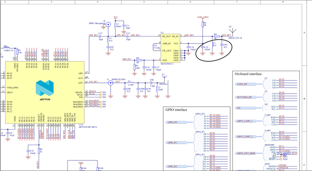
2. What is the second terminal of the capacitor and the inductor connected (refer the highlight in the image below) (P.S.: I am assuming it is connected to ground)

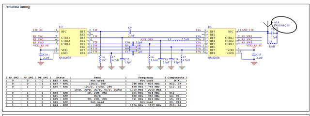
3. In the image below, since the antenna A1A FR01-S4-210 and the switch QM12038 both are matched to 50 ohm impedance, what is the need for the additional circuit connected to the antenna (I am assuming it is a antenna matching circuit :) )?
The help will be sincerely appreciated. Thank you!!!!

  • P.S.: The first image is taken from the schematic of the NRF9160 DevKit and the second image is taken from the schematic of the Thingy91

  • Yes I am aware of this that first one is from the schematic of nRF9160DK and the second image is taken from the schematic of thingy:91. I will give you a brief explanation soon. 

  • Hello,

    1. What does the N.C. stand for below inductor L5 and capacitor C85? (in the image below)

    N.C means non connected. 

    2. What is the second terminal of the capacitor and the inductor connected (refer the highlight in the image below) (P.S.: I am assuming it is connected to ground)

    Yes you are right. They are connected to second pin of the antenna.

    3. In the image below, since the antenna A1A FR01-S4-210 and the switch QM12038 both are matched to 50 ohm impedance, what is the need for the additional circuit connected to the antenna (I am assuming it is a antenna matching circuit :) )?

    Yes its a antenna matching circuit.

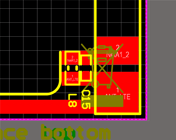
    The antenna tuner is all the components between and including U2 and U3 which are required to receive signals at different  LTE band. ANT_LTE is the output from the antenna tuner and is directly connected to the antenna. C15 and L8 are the antenna matching components.

    It is recommended to use radio matching network and antenna matching network for avoiding subdue harmonics and make sure that the signal in the transmission line is close to 50 ohms impedance. There is no 100% guarantee that the signal out from the ANT pin is 50ohms impedance. So, matching network is there to make sure that the signal sees as close as possible to a 50ohm impedance into the antenna. If there is a mismatch in impedance you can get a loos in power and reduced performance.

    Thanks.

    Best Regards,

    Kazi

  • Thank you!!!!  for your apt reply and support. It did really help me fast track my work.

  • It would a great help to me if you could help me with this question too (P.S.: I am sorry for asking this question late). Can I use the Qorvo QM12038 RF Switch (which is in the second image above) with Ethertronics P822601 LTE Antenna as this is available with me. Also is it possible to tune the antenna using the Qorvo RF Switch? If yes, do we need to change the values of the tuning circuit already present (in the second image above) and calculate the same for the Ethertronics antenna. Thank you!!!

Related