SAADC - Scan mode connects inputs to VDD_GPIO?

Hello!

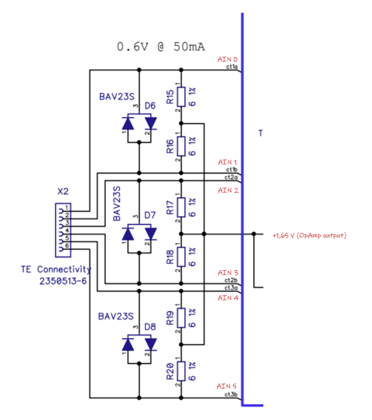
We are using a custom nRF9160 board with 3 differential ADC channels. The differential voltage is measured across two resistors, with the center voltage (normally OpAmp driven) at 1,66 V.

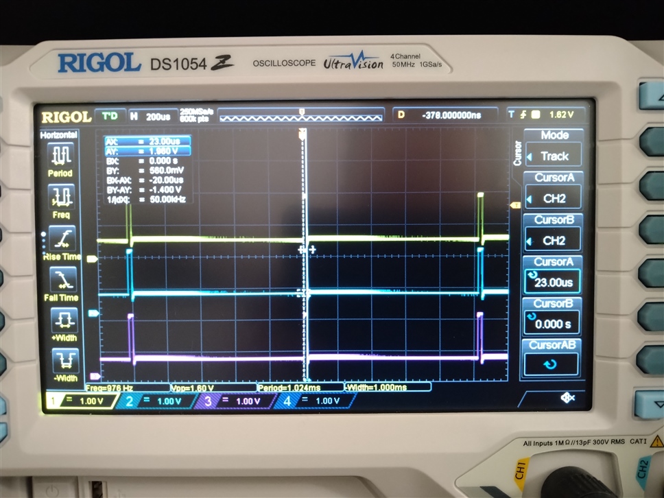
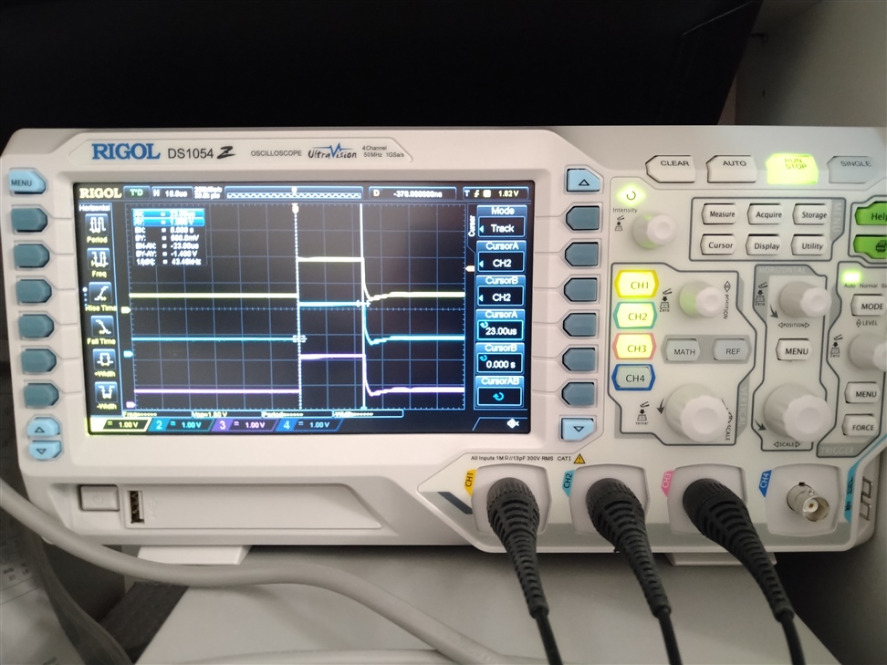
I'm sampling three ADC channels in differential mode and noticed weird results and verified with a scope: Taking a sample with more than one channel enabled results in nRF9160 connecting the ADC-inputs to what appears to be VDD-ish for a period that seems to be TACQ*2. Sampling is triggered by PPI, currently at 1 kHz, and this phenomenon happens at every sample. (Changing the PPI frequency changes the spike positions as well.

Changing to single-ended measurement makes no difference but the problem doesn't show on scope with only one channel enabled.

Do I have something wrong with my SAADC configuration?

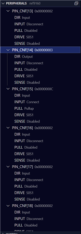
UPDATE 2022-10-24: Issue is related to CONFIG_BOOTLOADER_MCUBOOT and pin P0.14, which seems to configured as output and connecting to VDD_GPIO when it is sampling ADC

// SAADC Channel configuration
#define ADC_CONFIG_DIFF (SAADC_CH_CONFIG_GAIN_Gain1     << SAADC_CH_CONFIG_GAIN_Pos) | \
                        (SAADC_CH_CONFIG_MODE_Diff        << SAADC_CH_CONFIG_MODE_Pos) | \
                        (SAADC_CH_CONFIG_REFSEL_Internal  << SAADC_CH_CONFIG_REFSEL_Pos) | \
                        (SAADC_CH_CONFIG_RESN_Bypass      << SAADC_CH_CONFIG_RESN_Pos) | \
                        (SAADC_CH_CONFIG_RESP_Bypass      << SAADC_CH_CONFIG_RESP_Pos) | \
                        (SAADC_CH_CONFIG_TACQ_10us        << SAADC_CH_CONFIG_TACQ_Pos)

static void init_adc(void) {
  NRF_SAADC_NS->TASKS_CALIBRATEOFFSET = 1;
  
  NRF_SAADC_NS->RESOLUTION = SAADC_RESOLUTION_VAL_12bit;
  
  // Set sampling rate to be controlled by "SAMPLE", call.
  NRF_SAADC_NS->SAMPLERATE = SAADC_SAMPLERATE_MODE_Task;

  //Set the EasyDMA buffer
  active_buffer = 0;
  NRF_SAADC_NS->RESULT.PTR = (uint32_t) &m_sample_buffer_0;
  NRF_SAADC_NS->RESULT.MAXCNT = ADC_TOTAL_BUFFER_LEN;

  // Enable interrupt for buffer full
  NRF_SAADC_NS->INTENSET = SAADC_INTENSET_END_Set << SAADC_INTENSET_END_Pos;
  NRF_SAADC_NS->INTEN |= SAADC_INTEN_END_Enabled << SAADC_INTEN_END_Pos;
  NRF_SAADC_NS->EVENTS_END = 0;
  
// Configure SAADC Channels 
  NRF_SAADC_NS->CH[0].CONFIG = ADC_CONFIG_DIFF;
  NRF_SAADC_NS->CH[0].PSELP = SAADC_CH_PSELP_PSELP_AnalogInput0 << SAADC_CH_PSELP_PSELP_Pos;
  NRF_SAADC_NS->CH[0].PSELN = SAADC_CH_PSELN_PSELN_AnalogInput1 << SAADC_CH_PSELN_PSELN_Pos;


  NRF_SAADC_NS->CH[1].CONFIG = ADC_CONFIG_DIFF;
  NRF_SAADC_NS->CH[1].PSELP = SAADC_CH_PSELP_PSELP_AnalogInput2 << SAADC_CH_PSELP_PSELP_Pos;
  NRF_SAADC_NS->CH[1].PSELN = SAADC_CH_PSELN_PSELN_AnalogInput3 << SAADC_CH_PSELN_PSELN_Pos;


  NRF_SAADC_NS->CH[2].CONFIG = ADC_CONFIG_DIFF;
  NRF_SAADC_NS->CH[2].PSELP = SAADC_CH_PSELP_PSELP_AnalogInput4 << SAADC_CH_PSELP_PSELP_Pos;
  NRF_SAADC_NS->CH[2].PSELN = SAADC_CH_PSELN_PSELN_AnalogInput5 << SAADC_CH_PSELN_PSELN_Pos;

  
  NVIC_EnableIRQ( SAADC_IRQn );
  NVIC_SetPriority( SAADC_IRQn, 1UL );
  IRQ_DIRECT_CONNECT(SAADC_IRQn, 0, SAADC_IRQHandler, 0);
  NRF_SAADC_NS->ENABLE = 1;
}

Scope images (OpAmp off, resulting in ~0,7 V average at the OpAmp output)

Parents
  • Ok, feels like it's at least partly solved for now. With the debugger I found that the PIN_CNF -registers were not identical for AIN0 - AIN5, and the P0.14 was configured as Output.

    Setting the PIN_CNF -regs manually and the problem is gone...

    static void set_pin_cnf(uint8_t pin) {
      NRF_P0_NS->PIN_CNF[pin] = 
          (GPIO_PIN_CNF_DIR_Input         << GPIO_PIN_CNF_DIR_Pos) 
        ||(GPIO_PIN_CNF_INPUT_Connect     << GPIO_PIN_CNF_INPUT_Pos)
        ||(GPIO_PIN_CNF_PULL_Disabled     << GPIO_PIN_CNF_PULL_Pos)
        ||(GPIO_PIN_CNF_DRIVE_S0S1        << GPIO_PIN_CNF_DRIVE_Pos)
        ||(GPIO_PIN_CNF_SENSE_Disabled    << GPIO_PIN_CNF_SENSE_Pos);
    }

    I still don't know why exactly this is the case, as no other part of the code touches GPIO, UART1 is disabled and there's nothing in the devicetree about P0.14.

  • Hello Jyri,

    I am glad to read that you were able to figure out the root cause of this issue. If I could ask, what button are you using for your mcuboot-button0 alias?
    If the issue here is that the particular pin is used by mcuboot then it should indeed be visible in the devicetree - if you need this particular pin you could change the alias in the devicetree away from that particular pin as well.

    Best regards,
    Karl

  • That's peculiar.. does the behavior of the pin change if you add TFM_LOG_LEVEL_SILENCE=y in your prj.conf?
    Based on the compiled devicetree I would not expect so, but I ask just so that we can rule it out.

    Best regards,
    Karl

  • Hi,

    I'll test it when I have the time and report back.

  • Alright, great - no worries about the time, we'll continue this whenever you have the chance.
    If the behavior you are seeing changes with the inclusion of the TFM log disable while the compiled devicetree stays the same I'll create another minimal example to try and replicate and explain the behavior.

    Best regards,
    Karl

  • TFM_LOG_LEVEL_SILENCE=y had no effect. Here's a screenshot of the PIN_CNF registers, pins 14 and 15 are the ones which get configured differently so you are probably correct that it's UART1 related (though it is indeed disabled as seen while debugging registers):

  • Hello again,

    Thank you for your patience with this.

    I have looked further into this and discussed it with some colleagues, and we found this part about the TF-M logging.

    The default value should be adjusted based on the SILENCE config, but it does not seem to be the case with your application.

    The config for the logging directly reads:

    config TFM_SECURE_UART1
        bool "TF-M configure UART1 as secure peripheral"
        default y if !TFM_LOG_LEVEL_SILENCE
        depends on !UART_1_NRF_UARTE
        depends on !"$(dt_nodelabel_enabled,uart1)"
        depends on SOC_NRF5340_CPUAPP || SOC_NRF9160
        help
          Configure the UART1 peripheral as secure for TF-M logging.
          This makes the UART1 peripheral unavailable to the non-secure
          application. When this option is selected the device tree node for
          UART1 needs to be disabled for the non-secure application.

    Is this currently enabled in your build (despite the SILENCE config)? You can check this by writing TFM_SECURE_UART1 in your prj.conf and hoovering over it with your mouse, for instance.

    Best regards,
    Karl
Reply
  • Hello again,

    Thank you for your patience with this.

    I have looked further into this and discussed it with some colleagues, and we found this part about the TF-M logging.

    The default value should be adjusted based on the SILENCE config, but it does not seem to be the case with your application.

    The config for the logging directly reads:

    config TFM_SECURE_UART1
        bool "TF-M configure UART1 as secure peripheral"
        default y if !TFM_LOG_LEVEL_SILENCE
        depends on !UART_1_NRF_UARTE
        depends on !"$(dt_nodelabel_enabled,uart1)"
        depends on SOC_NRF5340_CPUAPP || SOC_NRF9160
        help
          Configure the UART1 peripheral as secure for TF-M logging.
          This makes the UART1 peripheral unavailable to the non-secure
          application. When this option is selected the device tree node for
          UART1 needs to be disabled for the non-secure application.

    Is this currently enabled in your build (despite the SILENCE config)? You can check this by writing TFM_SECURE_UART1 in your prj.conf and hoovering over it with your mouse, for instance.

    Best regards,
    Karl
Children
Related