Sensor stuck in loop after production.

Hi, we are doing mass production using PLT. And we have found that like 10% of the sensors are stuck in certain stage as seen in following power cycle images.

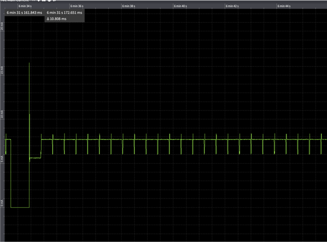
The program is stuck in this weird stage which looks like it is in a bootloader. After we program the sensor, we detach the power for MCU and attach the actual battery. While programmming, we confirmed that the sensors advertise. But when we put on the actual battery, It seems like it just stuck. I have never seen this issue before.

We tried to see if we can replicate the current consumption as seen in the image by putting some APP_ERROR_CHECK in the bootloader but we were not able to replicate it.(we are using nrf SDK 15.3)

Have you guys observed this issue before? If you guys did, what would be the issue?

  • Hello

    Looking at the plot, it seems like the cycle is a little less than 500 ms (?). So I'm thinking that maybe it's locked in a reset loop. LF crystals usually take about 250 - 500 ms to ramp up, and it is usually the first thing to start up after the BLE stack is enabled. If the application crashes right after this, then you could see a reset pattern that looks like the one in your plot. However, it is strange that this only happens to 10% of the sensors.

    To debug this further I have some questions:

    1. While programming, and confirming that the sensors are working, is this test performed while the chip is in debug mode? If it is, are you able to confirm if the failing sensors will work again in debug mode?
    2. I can see that the current is quite high. First, 500 ms of around 5 mA, then it jumps to 8 mA when it gets stuck.
      1. Is this 5 mA current the base current of the board? I.e. do you see the same 5 mA base current on the non-failing boards?
      2. The reason I ask is that the CPU current on the nRF52840 is around 3 mA, combined with a base current of 5 mA, the total current will be 8mA as seen in the plot, which could mean that the CPU is stuck in a loop.
    3. Anything in the firmware you are aware of that can explain the 500 ms loop?
    4. Are you using LFXO or LFRC?
    5. Is the DCDC regulator enabled?
    6. Can you please upload the board schematics? I can change this to a private case if you want, before uploading the schematic

    Thanks!

    Best regards,
    Stian

Related