Hi.
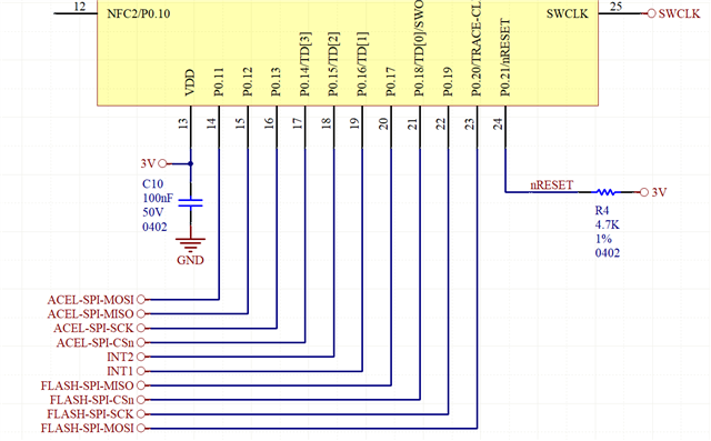
In my current project with nRF52832, I have used the following port pins to connect it to an accelerometer and a SPI flash memory:
I would like to ask, get opinions about:
(1) If all internal signals of all serial peripherals like SPIs, I2Cs and UARTS can be configured in firmware to be connected to any port/GPIO pin.
(2) If any port/GPIO pin can be used to wakeup the MCU from sleep mode through logic level changes on the pins.
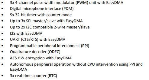
(3) The number of SPI peripherals? The number of I2C peripherals? The number of UART peripherals? And if they are shared? This is for future designs.
(4) If the schematic above is ok, regarding the 4-wire SPI signals of the 2 SPIs interfaces being connected to the nRF52832 pins P0.11~P0.14 and P0.17~P0.20, and if the INT1/INT2 push-pull outputs of the accelerometer which are connected to P0.15 and P0.16 can wakeup the nRF52832 from sleep mode through logic level changes on these pins.
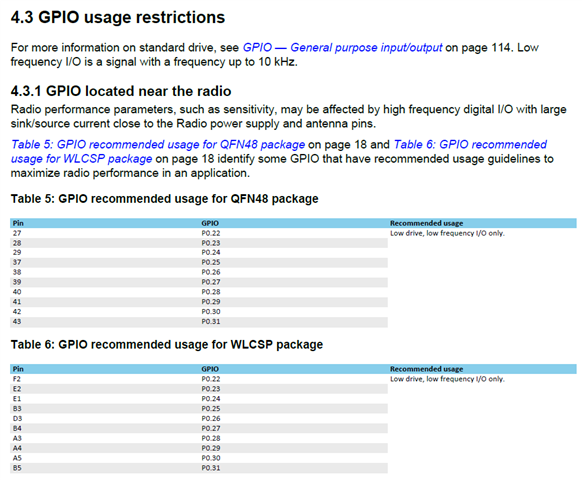
(5) By connecting the two SPI interface signals to the pins shown in the schematic above I'm following the recommendation from the nRF52832 Product Specification (shown below), which recommends the use of signals <=10KHz for ports P0.22 to P0.31, that are nearby radio signals or related. Actually all these pins are not used in my current design.
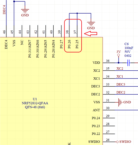
(6) P0.25 and P0.26 were connected to GND as a workaround, this was recommnded to me by Nordic support in past.
(7) What is the positive reference of the analog inputs / ADC? That is, for which input voltage the ADC result will have its maximum value? And what is the resolution (bits) of the ADC?
(8) In which situations is really needed the use of an external 32.768KHz crystal oscilator? Please correct me if I'm wrong with such statement: the nRF52832 has an internal "not-high-precision-low-frequency-oscillator" which can be used by its internal RTC to wakeup the MCU from sleep periodically or in a predefined interval/period/seconds/minutes/hours to ahead.
Regards,
Jeferson Pehls.