52832 timer and PWM interrupt

hi,

I want to use timer interrupt to start PWM function, and PWM had PWM interrupt too, hoping every 20ms to start PWM function, but if I open PWM and timer interrupt together, can't get normal wave, if I stop PWM interrupt, the wave is ok. I don't know reason. maybe I can't start PWM in the timer interrupt function?
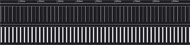
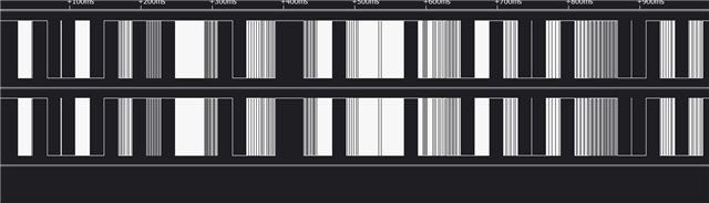
normal waveabnormal wave

timer interrupt 

void timer_led_event_handler(nrf_timer_event_t event_type, void* p_context)
{
	//bsp_board_led_invert(0);
	PWM init();	//---PWM init
}


PWM init

    APP_ERROR_CHECK(nrf_drv_pwm_init(&m_pwm0, &configTip0, NULL)); //--- normal wave
    APP_ERROR_CHECK(nrf_drv_pwm_init(&m_pwm1, &configRing0, NULL));//--- normal wave
//		
//	APP_ERROR_CHECK(nrf_drv_pwm_init(&m_pwm0, &configTip0, TipHandler));//--- abnormal wave
//	APP_ERROR_CHECK(nrf_drv_pwm_init(&m_pwm1, &configRing0, RingHandler));//--- abnormal wave

Parents
  • Hi,

    I am not able to explain this based on the information here, and generally it should not matter if you initialize PWM from an event handler (though that makes me wonder if you re-init it or perhaps something else you did not expect is happening)?. Perhaps you can elaborate a bit, bot about how things are failing, and perhaps more importantly add a bitt more code to provide context.

  • static void PWM_init(void)
    {
    
    	seq_values_Tip0[0] = seq_values_Tip[Count_Tip];
    	seq_values_Tip1[0] = seq_values_Tip[Count_Tip+1];
    	
    	seq_values_Ring0[0] = seq_values_Ring[Count_Ring];  
    	seq_values_Ring1[0] = seq_values_Ring[Count_Ring+1];  
    	
    	nrf_drv_pwm_config_t const configTip0 =
    	{
    			.output_pins =
    			{
    					BSP_LED_1 | NRF_DRV_PWM_PIN_INVERTED, // channel 0
    					NRF_DRV_PWM_PIN_NOT_USED,             // channel 1
    					NRF_DRV_PWM_PIN_NOT_USED,             // channel 2
    					NRF_DRV_PWM_PIN_NOT_USED,             // channel 3
    			},
    			.irq_priority = APP_IRQ_PRIORITY_LOWEST,
    			.base_clock   = NRF_PWM_CLK_16MHz,
    			.count_mode   = NRF_PWM_MODE_UP,
    			.top_value    = 0,												
    			.load_mode    = NRF_PWM_LOAD_WAVE_FORM,
    			.step_mode    = NRF_PWM_STEP_AUTO
    	};
    	nrf_drv_pwm_config_t const configRing0 =
    	{
    			.output_pins =
    			{
    					BSP_LED_0 | NRF_DRV_PWM_PIN_INVERTED, // channel 0
    					NRF_DRV_PWM_PIN_NOT_USED,             // channel 1
    					NRF_DRV_PWM_PIN_NOT_USED,             // channel 2
    					NRF_DRV_PWM_PIN_NOT_USED,             // channel 3
    			},
    			.irq_priority = APP_IRQ_PRIORITY_LOWEST,
    			.base_clock   = NRF_PWM_CLK_16MHz,
    			.count_mode   = NRF_PWM_MODE_UP,
    			.top_value    = 0,												
    			.load_mode    = NRF_PWM_LOAD_WAVE_FORM,
    			.step_mode    = NRF_PWM_STEP_AUTO
    	};
    	
    	ReleasePWM();
    
    //    APP_ERROR_CHECK(nrf_drv_pwm_init(&m_pwm0, &configTip0, NULL));
    //    APP_ERROR_CHECK(nrf_drv_pwm_init(&m_pwm1, &configRing0, NULL));
    //		
    	APP_ERROR_CHECK(nrf_drv_pwm_init(&m_pwm0, &configTip0, TipHandler));
    	APP_ERROR_CHECK(nrf_drv_pwm_init(&m_pwm1, &configRing0, RingHandler));
    
    	
    	m_used |= USED_PWM(0);
    	m_used |= USED_PWM(1);
    	
    	nrf_pwm_sequence_t const seq_Tip0 =
    	{
    			.values.p_wave_form = seq_values_Tip0,
    			.length          = NRF_PWM_VALUES_LENGTH(seq_values_Tip0),
    			.repeats         = number_Tip[Count_Tip]-1,
    			.end_delay       = 0
    	};
    	
    	 nrf_pwm_sequence_t const seq_Tip1 =
    	{
    			.values.p_wave_form = seq_values_Tip1,
    			.length          = NRF_PWM_VALUES_LENGTH(seq_values_Tip1),
    			.repeats         = number_Tip[Count_Tip+1]-1,
    			.end_delay       = 0
    	};
    		
    	nrf_pwm_sequence_t const seq_Ring0 =
    	{
    			.values.p_wave_form = seq_values_Ring0,
    			.length          = NRF_PWM_VALUES_LENGTH(seq_values_Ring0),
    			.repeats         = number_Ring[Count_Ring]-1,
    			.end_delay       = 0
    	};
    	
    	nrf_pwm_sequence_t const seq_Ring1 =
    	{
    			.values.p_wave_form = seq_values_Ring1,
    			.length          = NRF_PWM_VALUES_LENGTH(seq_values_Ring1),
    			.repeats         = number_Ring[Count_Ring+1]-1,
    			.end_delay       = 0
    	};
    
    	uint32_t start_pwm0_task_addr = nrf_drv_pwm_complex_playback(&m_pwm0, &seq_Tip0, &seq_Tip1, (sizeof(number_Tip)/sizeof(number_Tip[0])), NRFX_PWM_FLAG_STOP | NRF_DRV_PWM_FLAG_START_VIA_TASK|NRF_DRV_PWM_FLAG_SIGNAL_END_SEQ0 | NRF_DRV_PWM_FLAG_SIGNAL_END_SEQ1);               
    	uint32_t *start_pwm0_task = (uint32_t *) start_pwm0_task_addr;     
    	uint32_t start_pwm1_task_addr = nrf_drv_pwm_complex_playback(&m_pwm1, &seq_Ring0, &seq_Ring1, (sizeof(number_Ring)/sizeof(number_Ring[0])), NRFX_PWM_FLAG_STOP | NRF_DRV_PWM_FLAG_START_VIA_TASK|NRF_DRV_PWM_FLAG_SIGNAL_END_SEQ0 | NRF_DRV_PWM_FLAG_SIGNAL_END_SEQ1);               
       	uint32_t *start_pwm1_task = (uint32_t *) start_pwm1_task_addr;     
    	*start_pwm0_task = 1;   
    	*start_pwm1_task = 1;	
    
    }
    
    static void timer0_init(void)
    {
    	uint32_t time_ms = 20; //Time(in miliseconds) between consecutive compare events.
        uint32_t time_ticks;
        uint32_t err_code = NRF_SUCCESS;
    	
    		NRF_CLOCK->TASKS_HFCLKSTART = 1; // For more accurate timing. //start high speed clock
    
        //Configure TIMER_LED for generating simple light effect - leds on board will invert his state one after the other.
        nrf_drv_timer_config_t timer_cfg = NRF_DRV_TIMER_DEFAULT_CONFIG;
        err_code = nrf_drv_timer_init(&TIMER_LED, &timer_cfg, timer_led_event_handler);
        APP_ERROR_CHECK(err_code);
    
        time_ticks = nrf_drv_timer_ms_to_ticks(&TIMER_LED, time_ms);  //time_ticks = (times*16000)/512 = 31250
    
        nrf_drv_timer_extended_compare(
             &TIMER_LED, NRF_TIMER_CC_CHANNEL0, time_ticks, NRF_TIMER_SHORT_COMPARE0_CLEAR_MASK, true);
    
        nrf_drv_timer_enable(&TIMER_LED);
    
    }
    
    int main(void)
    { 
    	timer0_init();
        while (1)
        {
            //__WFI();
    			
    			 // Wait for an event.
            __WFE();
    
            // Clear the event register.
            __SEV();
            __WFE();
        }
    }

    this is PWM, timer0 init code and main code

  • Hi,

    Where is Count_Tip defined? As it is used in TipHandler but not defined there I assume it is intentionally global but not part of the code you copy-pasted (or if not you will get a warning). This will be incremented by 2 every time the interrupt handler runs and the event is NRFX_PWM_EVT_END_SEQ0, so this will quickly get a high number, and when you subsequently use it to pick an element of the seq_values_Tip array I that will be out of bounds, so the data will be invalid (whatever is there in RAM).

Reply
  • Hi,

    Where is Count_Tip defined? As it is used in TipHandler but not defined there I assume it is intentionally global but not part of the code you copy-pasted (or if not you will get a warning). This will be incremented by 2 every time the interrupt handler runs and the event is NRFX_PWM_EVT_END_SEQ0, so this will quickly get a high number, and when you subsequently use it to pick an element of the seq_values_Tip array I that will be out of bounds, so the data will be invalid (whatever is there in RAM).

Children
No Data
Related