Help connecting I2C temperature sensor to nRF9160DK

Hi Nordic Team

I have been successfully using the nRF52840DK to create various Bluetooth sensors, including a thermometer sensor.

I bought a nRF9160DK with the intent to create an IoT thermometer sensor using NB-IoT.

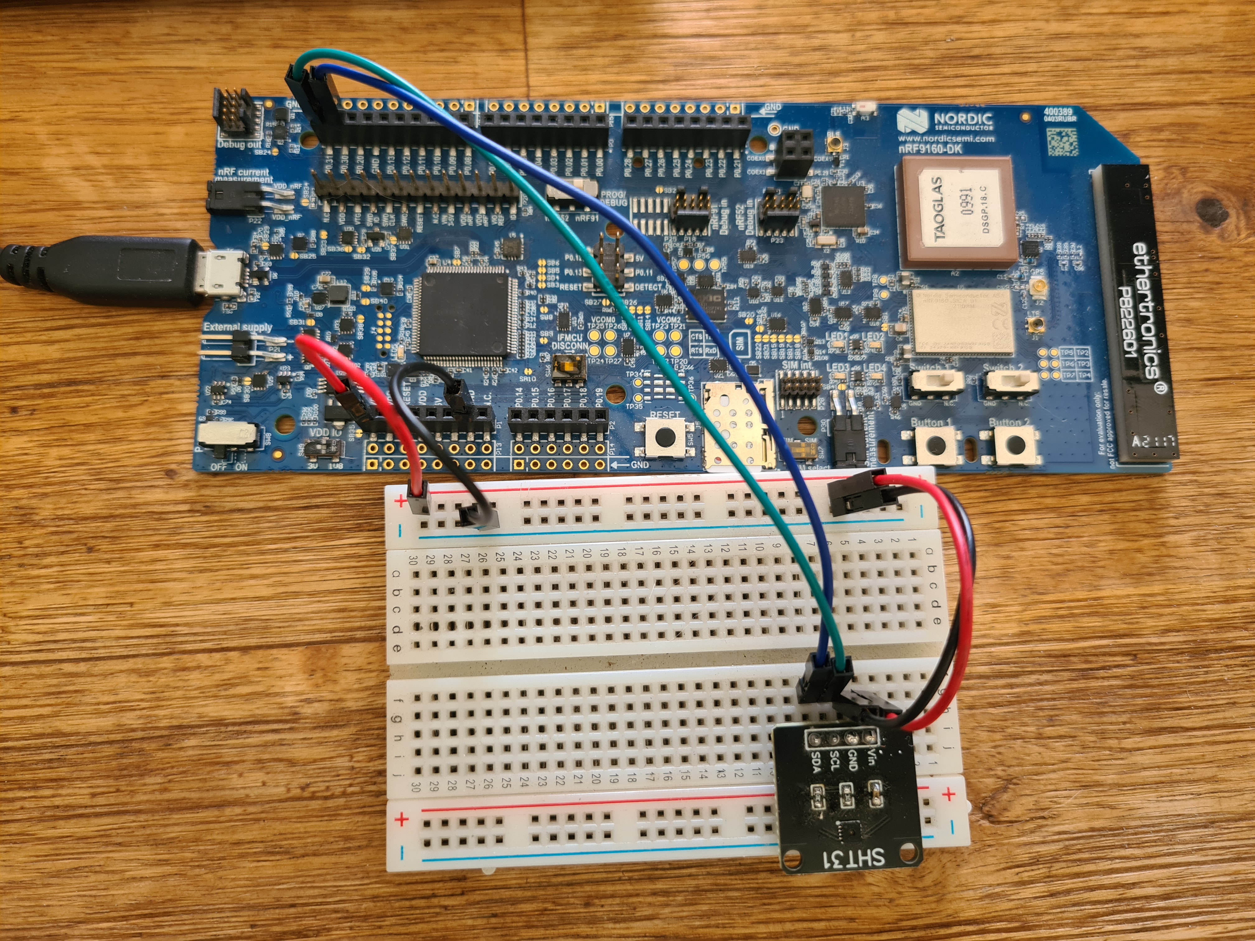
I am having trouble getting the nRF9160 to recognise/find the attached SHT31 sensor. I have used this exact same sensor with the 52840 Dev Kit without any issues, so I thought connecting it to the 9160DK should be simple...

I have tried a number of different approaches but I can't seem to get this working. Could you please have a look and let me know if I am doing anything wrong with the setup or connecting the sensor to the 9160DK?

I created a very basic app (attached) which I think should include all the elements to get this sensor identified and connected. The app compiles but the output is always "Could not get SHT3XD device".

I have tested the sensor on another board (not a 9160DK) and it is working. 

The sensor datasheet says it can operate from 2.5v to 5.5v so I tried switching between 1.8v and 3v using SW9 on the 9160DK with no change.

There is definitely voltage going to the sensor. I even tested the wires and they are all fine. Not sure what else to look for.
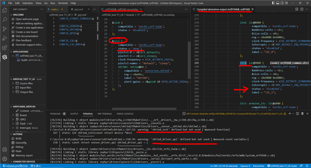
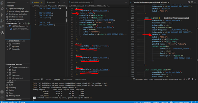
Overlay file:

&pinctrl {

    i2c1_default: i2c1_default {
        group1 {
            psels = <NRF_PSEL(TWIM_SDA, 0, 30)>,
                <NRF_PSEL(TWIM_SCL, 0, 31)>;
        };
    };

    i2c1_sleep: i2c1_sleep {
        group1 {
            psels = <NRF_PSEL(TWIM_SDA, 0, 30)>,
                <NRF_PSEL(TWIM_SCL, 0, 31)>;
            low-power-enable;
        };
    };
};

&i2c0 {
    compatible = "nordic,nrf-twim";
    status = "disabled";    
};

&i2c1 {
    compatible = "nordic,nrf-twim";
    status = "okay";
    pinctrl-0 = <&i2c1_default>;
    pinctrl-1 = <&i2c1_sleep>;
    clock-frequency = <I2C_BITRATE_FAST>;
    pinctrl-names = "default", "sleep";
    SHT3XD: sht3xd@44 {
        compatible = "sensirion,sht3xd";
        reg = <0x44>;
        label = "SHT3XD";
        alert-gpios = <&gpio0 10 GPIO_ACTIVE_HIGH>;    
    };
};

prj.conf file:

CONFIG_STDOUT_CONSOLE=y

CONFIG_SENSOR=y
CONFIG_SHT3XD=y
CONFIG_GPIO=y

CONFIG_I2C=y
CONFIG_I2C_NRFX=y
main.c
#include <zephyr.h>

#include <device.h>
#include <drivers/sensor.h>
#include <drivers/gpio.h>
#include <stdio.h>

void main(void)
{
    printk("Starting ST_T1_LR...\n");
   
    const struct device *thermometer_dev;
    struct sensor_value temp, hum;  
    double temperature, humidity;

    thermometer_dev = device_get_binding("SHT3XD");

    if (thermometer_dev == NULL) {
        printf("Could not get SHT3XD device\n");        
    }
    else{
        printk("Thermometer Ready\n");
    }  

    printk("starting loop\n");

    while (true) {

        k_sleep(K_MSEC(1000));

        printk("looping...\n");
       
    }
}

Any help would be very much apprecaited.

Regards

Garysht31.zip

  • Hi

    Just a little more info.

    I have tested the attached sample app on the nRF52840DK successfully. I just added an overlay specifically for the 52840 and all I changed in the overlay were the SDA/SCL pin numbers to 26/27. 

    I should have mentioned that I am using SDK 2.0.0 with VS Code.

    Regards,

    Gary

  • Hi Gary,

    I will look into your case and will update you accordingly. Thank you for providing more information.

    Naeem

  • Hi Gary,

    Thank you for contacting DevZone at NordicSemi.

    Your query is regarding using an overlay file to connect a (temperature) sensor to I2C of nRF9160DK.

    Thank you for attaching your files. When I compiled your project, it showed me warnings (shown in the image1 as well) that the "sht3xd_init" is defined but not used.

    As per your overlay file, you are connecting your sensor to to I2C1. When I looked at the complied device-tree, I found that I2C1 port is disabled. You can see all this in the image1.

    image1

    I kept all other things same and updated the overlay-file. So basically, our I2C1 was not getting enabled, but rather some other ports were getting enabled, which were in conflict with our requirements. Therefore, I had to disable them in the overlay. 

    You can see in the image2 below, which is showing the compiled device tree after changing the overlay file. We can see that I2C1 is enabled and connected to the sensor.

    image2:

    I am attaching overlay file for your reference. Hope it helps.

    N.B: I have moved the overlay file outside of the boards folder and placed directly in the project folder (where we have prj.conf).

    Regards,
    Naeem

  • Hi Naeem

    Thank you very much for your detailed response.

    Unfortunately, I am very confused because I don't see the same results in the build output or the compiled device tree that you have.

    My build output doesn't mention "sht3xd_init" is defined but not used and my overlay file shows that the I2C1 is "okay".

    I have attached the both files from my side.

    I assume the compiled device tree is the zephyr.dts file in the build folder?

    (I have renamed zephyr.dts to zephyr.txt to upload it here as your system won't accept a .dts file).

    I have also moved the .overlay file to the project folder and used your overlay file as the template but it is still failing to detect the sensor.

    Can you let me know what version of the SDK you are using? Perhaps something is wrong with my version (2.0.0) that is causing issues?

    Lastly, can you please let me know what is in conflict that is fixed with your .overlay file?

    In the nRF9160 Product Specification (v2.0) in section 6.17.1 it talks about shared resources and the need to disable peripherals with the same ID. In the Instantiation table (4.2.2) on page 24 it shows the address for the TWIM1 interface as 0x50009000 which is shared with SPIM1 and UART1, both of which are disabled in my device tree.

    Have I missed something?

    Thanks for your help.

    8836.Build Output.txt

    /dts-v1/;
    
    / {
    	#address-cells = < 0x1 >;
    	#size-cells = < 0x1 >;
    	model = "Nordic nRF9160 DK NRF9160";
    	compatible = "nordic,nrf9160-dk-nrf9160";
    	chosen {
    		zephyr,flash-controller = &flash_controller;
    		zephyr,entropy = &cryptocell_sw;
    		zephyr,console = &uart0;
    		zephyr,shell-uart = &uart0;
    		zephyr,uart-mcumgr = &uart0;
    		zephyr,flash = &flash0;
    		zephyr,sram = &sram0_ns;
    		zephyr,code-partition = &slot0_ns_partition;
    	};
    	aliases {
    		led0 = &led0;
    		led1 = &led1;
    		led2 = &led2;
    		led3 = &led3;
    		pwm-led0 = &pwm_led0;
    		sw0 = &button0;
    		sw1 = &button1;
    		sw2 = &button2;
    		sw3 = &button3;
    		bootloader-led0 = &led0;
    	};
    	soc {
    		#address-cells = < 0x1 >;
    		#size-cells = < 0x1 >;
    		compatible = "nordic,nRF9160-SICA", "nordic,nRF9160", "nordic,nRF91", "simple-bus";
    		interrupt-parent = < &nvic >;
    		ranges;
    		nvic: interrupt-controller@e000e100 {
    			#address-cells = < 0x1 >;
    			compatible = "arm,v8m-nvic";
    			reg = < 0xe000e100 0xc00 >;
    			interrupt-controller;
    			#interrupt-cells = < 0x2 >;
    			arm,num-irq-priority-bits = < 0x3 >;
    			phandle = < 0x1 >;
    		};
    		systick: timer@e000e010 {
    			compatible = "arm,armv8m-systick";
    			reg = < 0xe000e010 0x10 >;
    			status = "disabled";
    		};
    		sram0: memory@20000000 {
    			compatible = "mmio-sram";
    			reg = < 0x20000000 0x40000 >;
    		};
    		peripheral@40000000 {
    			#address-cells = < 0x1 >;
    			#size-cells = < 0x1 >;
    			ranges = < 0x0 0x40000000 0x10000000 >;
    			flash_controller: flash-controller@39000 {
    				compatible = "nordic,nrf91-flash-controller";
    				reg = < 0x39000 0x1000 >;
    				partial-erase;
    				#address-cells = < 0x1 >;
    				#size-cells = < 0x1 >;
    				label = "NRF_FLASH_DRV_NAME";
    				flash0: flash@0 {
    					compatible = "soc-nv-flash";
    					label = "NRF_FLASH";
    					erase-block-size = < 0x1000 >;
    					write-block-size = < 0x4 >;
    					reg = < 0x0 0x100000 >;
    					partitions {
    						compatible = "fixed-partitions";
    						#address-cells = < 0x1 >;
    						#size-cells = < 0x1 >;
    						boot_partition: partition@0 {
    							label = "mcuboot";
    							reg = < 0x0 0x10000 >;
    						};
    						slot0_partition: partition@10000 {
    							label = "image-0";
    							reg = < 0x10000 0x40000 >;
    						};
    						slot0_ns_partition: partition@50000 {
    							label = "image-0-nonsecure";
    							reg = < 0x50000 0x30000 >;
    						};
    						slot1_partition: partition@80000 {
    							label = "image-1";
    							reg = < 0x80000 0x40000 >;
    						};
    						slot1_ns_partition: partition@c0000 {
    							label = "image-1-nonsecure";
    							reg = < 0xc0000 0x30000 >;
    						};
    						scratch_partition: partition@f0000 {
    							label = "image-scratch";
    							reg = < 0xf0000 0xa000 >;
    						};
    						storage_partition: partition@fa000 {
    							label = "storage";
    							reg = < 0xfa000 0x6000 >;
    						};
    					};
    				};
    			};
    			adc: adc@e000 {
    				compatible = "nordic,nrf-saadc";
    				reg = < 0xe000 0x1000 >;
    				interrupts = < 0xe 0x1 >;
    				status = "okay";
    				label = "ADC_0";
    				#io-channel-cells = < 0x1 >;
    				phandle = < 0x13 >;
    			};
    			dppic: dppic@17000 {
    				compatible = "nordic,nrf-dppic";
    				reg = < 0x17000 0x1000 >;
    				status = "okay";
    				label = "DPPIC";
    			};
    			egu0: egu@1b000 {
    				compatible = "nordic,nrf-egu";
    				reg = < 0x1b000 0x1000 >;
    				interrupts = < 0x1b 0x1 >;
    				status = "okay";
    			};
    			egu1: egu@1c000 {
    				compatible = "nordic,nrf-egu";
    				reg = < 0x1c000 0x1000 >;
    				interrupts = < 0x1c 0x1 >;
    				status = "okay";
    			};
    			egu2: egu@1d000 {
    				compatible = "nordic,nrf-egu";
    				reg = < 0x1d000 0x1000 >;
    				interrupts = < 0x1d 0x1 >;
    				status = "okay";
    			};
    			egu3: egu@1e000 {
    				compatible = "nordic,nrf-egu";
    				reg = < 0x1e000 0x1000 >;
    				interrupts = < 0x1e 0x1 >;
    				status = "okay";
    			};
    			egu4: egu@1f000 {
    				compatible = "nordic,nrf-egu";
    				reg = < 0x1f000 0x1000 >;
    				interrupts = < 0x1f 0x1 >;
    				status = "okay";
    			};
    			egu5: egu@20000 {
    				compatible = "nordic,nrf-egu";
    				reg = < 0x20000 0x1000 >;
    				interrupts = < 0x20 0x1 >;
    				status = "okay";
    			};
    			ipc: ipc@2a000 {
    				compatible = "nordic,nrf-ipc";
    				reg = < 0x2a000 0x1000 >;
    				interrupts = < 0x2a 0x1 >;
    				status = "okay";
    				label = "IPC";
    			};
    			i2s0: i2s@28000 {
    				compatible = "nordic,nrf-i2s";
    				#address-cells = < 0x1 >;
    				#size-cells = < 0x0 >;
    				reg = < 0x28000 0x1000 >;
    				interrupts = < 0x28 0x1 >;
    				status = "disabled";
    				label = "I2S_0";
    			};
    			kmu: kmu@39000 {
    				compatible = "nordic,nrf-kmu";
    				reg = < 0x39000 0x1000 >;
    				interrupts = < 0x39 0x1 >;
    				status = "okay";
    			};
    			pdm0: pdm@26000 {
    				compatible = "nordic,nrf-pdm";
    				reg = < 0x26000 0x1000 >;
    				interrupts = < 0x26 0x1 >;
    				status = "disabled";
    				label = "PDM_0";
    			};
    			regulators: regulator@4000 {
    				compatible = "nordic,nrf-regulators";
    				reg = < 0x4000 0x1000 >;
    				status = "okay";
    			};
    			vmc: vmc@3a000 {
    				compatible = "nordic,nrf-vmc";
    				reg = < 0x3a000 0x1000 >;
    				status = "okay";
    			};
    			uart0: uart@8000 {
    				compatible = "nordic,nrf-uarte";
    				reg = < 0x8000 0x1000 >;
    				interrupts = < 0x8 0x1 >;
    				status = "okay";
    				label = "UART_0";
    				current-speed = < 0x1c200 >;
    				pinctrl-0 = < &uart0_default >;
    				pinctrl-1 = < &uart0_sleep >;
    				pinctrl-names = "default", "sleep";
    			};
    			uart1: arduino_serial: uart@9000 {
    				compatible = "nordic,nrf-uarte";
    				reg = < 0x9000 0x1000 >;
    				interrupts = < 0x9 0x1 >;
    				status = "disabled";
    				label = "UART_1";
    				current-speed = < 0x1c200 >;
    				pinctrl-0 = < &uart1_default >;
    				pinctrl-1 = < &uart1_sleep >;
    				pinctrl-names = "default", "sleep";
    			};
    			uart2: uart@a000 {
    				compatible = "nordic,nrf-uarte";
    				reg = < 0xa000 0x1000 >;
    				interrupts = < 0xa 0x1 >;
    				status = "disabled";
    				label = "UART_2";
    				pinctrl-0 = < &uart2_default >;
    				pinctrl-1 = < &uart2_sleep >;
    				pinctrl-names = "default", "sleep";
    			};
    			uart3: uart@b000 {
    				compatible = "nordic,nrf-uarte";
    				reg = < 0xb000 0x1000 >;
    				interrupts = < 0xb 0x1 >;
    				status = "disabled";
    				label = "UART_3";
    			};
    			i2c0: i2c@8000 {
    				compatible = "nordic,nrf-twim";
    				#address-cells = < 0x1 >;
    				#size-cells = < 0x0 >;
    				reg = < 0x8000 0x1000 >;
    				clock-frequency = < 0x186a0 >;
    				interrupts = < 0x8 0x1 >;
    				status = "disabled";
    				label = "I2C_0";
    			};
    			i2c1: i2c@9000 {
    				compatible = "nordic,nrf-twim";
    				#address-cells = < 0x1 >;
    				#size-cells = < 0x0 >;
    				reg = < 0x9000 0x1000 >;
    				clock-frequency = < 0x61a80 >;
    				interrupts = < 0x9 0x1 >;
    				status = "okay";
    				label = "I2C_1";
    				pinctrl-0 = < &i2c1_default >;
    				pinctrl-1 = < &i2c1_sleep >;
    				pinctrl-names = "default", "sleep";
    				SHT3XD: sht3xd@44 {
    					compatible = "sensirion,sht3xd";
    					reg = < 0x44 >;
    					label = "SHT3XD";
    					alert-gpios = < &gpio0 0xa 0x0 >;
    				};
    			};
    			i2c2: arduino_i2c: i2c@a000 {
    				compatible = "nordic,nrf-twim";
    				#address-cells = < 0x1 >;
    				#size-cells = < 0x0 >;
    				reg = < 0xa000 0x1000 >;
    				clock-frequency = < 0x186a0 >;
    				interrupts = < 0xa 0x1 >;
    				status = "okay";
    				label = "I2C_2";
    				pinctrl-0 = < &i2c2_default >;
    				pinctrl-1 = < &i2c2_sleep >;
    				pinctrl-names = "default", "sleep";
    			};
    			i2c3: i2c@b000 {
    				compatible = "nordic,nrf-twim";
    				#address-cells = < 0x1 >;
    				#size-cells = < 0x0 >;
    				reg = < 0xb000 0x1000 >;
    				clock-frequency = < 0x186a0 >;
    				interrupts = < 0xb 0x1 >;
    				status = "disabled";
    				label = "I2C_3";
    			};
    			spi0: spi@8000 {
    				compatible = "nordic,nrf-spim";
    				#address-cells = < 0x1 >;
    				#size-cells = < 0x0 >;
    				reg = < 0x8000 0x1000 >;
    				interrupts = < 0x8 0x1 >;
    				status = "disabled";
    				label = "SPI_0";
    			};
    			spi1: spi@9000 {
    				compatible = "nordic,nrf-spim";
    				#address-cells = < 0x1 >;
    				#size-cells = < 0x0 >;
    				reg = < 0x9000 0x1000 >;
    				interrupts = < 0x9 0x1 >;
    				status = "disabled";
    				label = "SPI_1";
    			};
    			spi2: spi@a000 {
    				compatible = "nordic,nrf-spim";
    				#address-cells = < 0x1 >;
    				#size-cells = < 0x0 >;
    				reg = < 0xa000 0x1000 >;
    				interrupts = < 0xa 0x1 >;
    				status = "disabled";
    				label = "SPI_2";
    			};
    			spi3: spi@b000 {
    				compatible = "nordic,nrf-spim";
    				#address-cells = < 0x1 >;
    				#size-cells = < 0x0 >;
    				reg = < 0xb000 0x1000 >;
    				interrupts = < 0xb 0x1 >;
    				status = "okay";
    				label = "SPI_3";
    				pinctrl-0 = < &spi3_default >;
    				pinctrl-1 = < &spi3_sleep >;
    				pinctrl-names = "default", "sleep";
    			};
    			pwm0: pwm@21000 {
    				compatible = "nordic,nrf-pwm";
    				reg = < 0x21000 0x1000 >;
    				interrupts = < 0x21 0x1 >;
    				status = "okay";
    				label = "PWM_0";
    				#pwm-cells = < 0x3 >;
    				pinctrl-0 = < &pwm0_default >;
    				pinctrl-1 = < &pwm0_sleep >;
    				pinctrl-names = "default", "sleep";
    				phandle = < 0x11 >;
    			};
    			pwm1: pwm@22000 {
    				compatible = "nordic,nrf-pwm";
    				reg = < 0x22000 0x1000 >;
    				interrupts = < 0x22 0x1 >;
    				status = "disabled";
    				label = "PWM_1";
    				#pwm-cells = < 0x3 >;
    			};
    			pwm2: pwm@23000 {
    				compatible = "nordic,nrf-pwm";
    				reg = < 0x23000 0x1000 >;
    				interrupts = < 0x23 0x1 >;
    				status = "disabled";
    				label = "PWM_2";
    				#pwm-cells = < 0x3 >;
    			};
    			pwm3: pwm@24000 {
    				compatible = "nordic,nrf-pwm";
    				reg = < 0x24000 0x1000 >;
    				interrupts = < 0x24 0x1 >;
    				status = "disabled";
    				label = "PWM_3";
    				#pwm-cells = < 0x3 >;
    			};
    			gpio0: gpio@842500 {
    				compatible = "nordic,nrf-gpio";
    				gpio-controller;
    				reg = < 0x842500 0x300 >;
    				#gpio-cells = < 0x2 >;
    				label = "GPIO_0";
    				status = "okay";
    				port = < 0x0 >;
    				phandle = < 0xa >;
    			};
    			rtc0: rtc@14000 {
    				compatible = "nordic,nrf-rtc";
    				reg = < 0x14000 0x1000 >;
    				cc-num = < 0x4 >;
    				interrupts = < 0x14 0x1 >;
    				status = "okay";
    				clock-frequency = < 0x8000 >;
    				prescaler = < 0x1 >;
    				label = "RTC_0";
    			};
    			rtc1: rtc@15000 {
    				compatible = "nordic,nrf-rtc";
    				reg = < 0x15000 0x1000 >;
    				cc-num = < 0x4 >;
    				interrupts = < 0x15 0x1 >;
    				status = "okay";
    				clock-frequency = < 0x8000 >;
    				prescaler = < 0x1 >;
    				label = "RTC_1";
    			};
    			clock: clock@5000 {
    				compatible = "nordic,nrf-clock";
    				reg = < 0x5000 0x1000 >;
    				interrupts = < 0x5 0x1 >;
    				status = "okay";
    				label = "CLOCK";
    			};
    			power: power@5000 {
    				compatible = "nordic,nrf-power";
    				reg = < 0x5000 0x1000 >;
    				interrupts = < 0x5 0x1 >;
    				status = "okay";
    			};
    			wdt: wdt0: watchdog@18000 {
    				compatible = "nordic,nrf-wdt";
    				reg = < 0x18000 0x1000 >;
    				interrupts = < 0x18 0x1 >;
    				status = "okay";
    				label = "WDT";
    			};
    			timer0: timer@f000 {
    				compatible = "nordic,nrf-timer";
    				status = "okay";
    				reg = < 0xf000 0x1000 >;
    				cc-num = < 0x6 >;
    				interrupts = < 0xf 0x1 >;
    				prescaler = < 0x0 >;
    				label = "TIMER_0";
    			};
    			timer1: timer@10000 {
    				compatible = "nordic,nrf-timer";
    				status = "okay";
    				reg = < 0x10000 0x1000 >;
    				cc-num = < 0x6 >;
    				interrupts = < 0x10 0x1 >;
    				prescaler = < 0x0 >;
    				label = "TIMER_1";
    			};
    			timer2: timer@11000 {
    				compatible = "nordic,nrf-timer";
    				status = "okay";
    				reg = < 0x11000 0x1000 >;
    				cc-num = < 0x6 >;
    				interrupts = < 0x11 0x1 >;
    				prescaler = < 0x0 >;
    				label = "TIMER_2";
    			};
    		};
    		gpiote: gpiote@40031000 {
    			compatible = "nordic,nrf-gpiote";
    			reg = < 0x40031000 0x1000 >;
    			interrupts = < 0x31 0x5 >;
    			status = "okay";
    			label = "GPIOTE_1";
    		};
    	};
    	pinctrl: pin-controller {
    		compatible = "nordic,nrf-pinctrl";
    		uart0_default: uart0_default {
    			phandle = < 0x2 >;
    			group1 {
    				psels = < 0x1d >, < 0x2001b >;
    			};
    			group2 {
    				psels = < 0x1001c >, < 0x3001a >;
    				bias-pull-up;
    			};
    		};
    		uart0_sleep: uart0_sleep {
    			phandle = < 0x3 >;
    			group1 {
    				psels = < 0x1d >, < 0x1001c >, < 0x2001b >, < 0x3001a >;
    				low-power-enable;
    			};
    		};
    		uart1_default: uart1_default {
    			phandle = < 0x4 >;
    			group1 {
    				psels = < 0x1 >, < 0x2000e >;
    			};
    			group2 {
    				psels = < 0x10000 >, < 0x3000f >;
    				bias-pull-up;
    			};
    		};
    		uart1_sleep: uart1_sleep {
    			phandle = < 0x5 >;
    			group1 {
    				psels = < 0x1 >, < 0x10000 >, < 0x2000e >, < 0x3000f >;
    				low-power-enable;
    			};
    		};
    		uart2_default: uart2_default {
    			phandle = < 0x6 >;
    			group1 {
    				psels = < 0x18 >, < 0x10017 >;
    			};
    		};
    		uart2_sleep: uart2_sleep {
    			phandle = < 0x7 >;
    			group1 {
    				psels = < 0x18 >, < 0x10017 >;
    				low-power-enable;
    			};
    		};
    		i2c2_default: i2c2_default {
    			phandle = < 0xb >;
    			group1 {
    				psels = < 0xc001e >, < 0xb001f >;
    			};
    		};
    		i2c2_sleep: i2c2_sleep {
    			phandle = < 0xc >;
    			group1 {
    				psels = < 0xc001e >, < 0xb001f >;
    				low-power-enable;
    			};
    		};
    		pwm0_default: pwm0_default {
    			phandle = < 0xf >;
    			group1 {
    				psels = < 0x160002 >;
    			};
    		};
    		pwm0_sleep: pwm0_sleep {
    			phandle = < 0x10 >;
    			group1 {
    				psels = < 0x160002 >;
    				low-power-enable;
    			};
    		};
    		spi3_default: spi3_default {
    			phandle = < 0xd >;
    			group1 {
    				psels = < 0x40013 >, < 0x50012 >, < 0x60011 >;
    			};
    		};
    		spi3_sleep: spi3_sleep {
    			phandle = < 0xe >;
    			group1 {
    				psels = < 0x40013 >, < 0x50012 >, < 0x60011 >;
    				low-power-enable;
    			};
    		};
    		i2c1_default: i2c1_default {
    			phandle = < 0x8 >;
    			group1 {
    				psels = < 0xc001e >, < 0xb001f >;
    			};
    		};
    		i2c1_sleep: i2c1_sleep {
    			phandle = < 0x9 >;
    			group1 {
    				psels = < 0xc001e >, < 0xb001f >;
    				low-power-enable;
    			};
    		};
    	};
    	rng_hci: entropy_bt_hci {
    		compatible = "zephyr,bt-hci-entropy";
    		label = "bt_hci_entropy";
    		status = "okay";
    	};
    	cpus {
    		#address-cells = < 0x1 >;
    		#size-cells = < 0x0 >;
    		cpu@0 {
    			device_type = "cpu";
    			compatible = "arm,cortex-m33f";
    			reg = < 0x0 >;
    			#address-cells = < 0x1 >;
    			#size-cells = < 0x1 >;
    			mpu: mpu@e000ed90 {
    				compatible = "arm,armv8m-mpu";
    				reg = < 0xe000ed90 0x40 >;
    				arm,num-mpu-regions = < 0x10 >;
    			};
    		};
    	};
    	cryptocell_sw: cryptocell-sw {
    		compatible = "nordic,nrf-cc310-sw";
    		label = "CRYPTOCELL_SW";
    		status = "okay";
    	};
    	leds {
    		compatible = "gpio-leds";
    		led0: led_0 {
    			gpios = < &gpio0 0x2 0x0 >;
    			label = "Green LED 1";
    		};
    		led1: led_1 {
    			gpios = < &gpio0 0x3 0x0 >;
    			label = "Green LED 2";
    		};
    		led2: led_2 {
    			gpios = < &gpio0 0x4 0x0 >;
    			label = "Green LED 3";
    		};
    		led3: led_3 {
    			gpios = < &gpio0 0x5 0x0 >;
    			label = "Green LED 4";
    		};
    	};
    	pwmleds {
    		compatible = "pwm-leds";
    		pwm_led0: pwm_led_0 {
    			pwms = < &pwm0 0x0 0x1312d00 0x0 >;
    		};
    	};
    	buttons {
    		compatible = "gpio-keys";
    		button0: button_0 {
    			gpios = < &gpio0 0x6 0x11 >;
    			label = "Push button 1";
    		};
    		button1: button_1 {
    			gpios = < &gpio0 0x7 0x11 >;
    			label = "Push button 2";
    		};
    		button2: button_2 {
    			gpios = < &gpio0 0x8 0x11 >;
    			label = "Switch 1";
    		};
    		button3: button_3 {
    			gpios = < &gpio0 0x9 0x11 >;
    			label = "Switch 2";
    		};
    	};
    	interface_to_nrf52840: gpio-interface {
    		compatible = "nordic,nrf9160dk-nrf52840-interface";
    		#gpio-cells = < 0x2 >;
    		gpio-map-mask = < 0xf 0x0 >;
    		gpio-map-pass-thru = < 0x0 0xffffffff >;
    		gpio-map = < 0x0 0x0 &gpio0 0x11 0x0 >, < 0x1 0x0 &gpio0 0x12 0x0 >, < 0x2 0x0 &gpio0 0x13 0x0 >, < 0x3 0x0 &gpio0 0x15 0x0 >, < 0x4 0x0 &gpio0 0x16 0x0 >, < 0x5 0x0 &gpio0 0x17 0x0 >;
    		phandle = < 0x12 >;
    	};
    	nrf52840_reset: gpio-reset {
    		compatible = "nordic,nrf9160dk-nrf52840-reset";
    		status = "disabled";
    		gpios = < &interface_to_nrf52840 0x5 0x0 >;
    	};
    	arduino_header: connector {
    		compatible = "arduino-header-r3";
    		#gpio-cells = < 0x2 >;
    		gpio-map-mask = < 0xffffffff 0xffffffc0 >;
    		gpio-map-pass-thru = < 0x0 0x3f >;
    		gpio-map = < 0x0 0x0 &gpio0 0xe 0x0 >, < 0x1 0x0 &gpio0 0xf 0x0 >, < 0x2 0x0 &gpio0 0x10 0x0 >, < 0x3 0x0 &gpio0 0x11 0x0 >, < 0x4 0x0 &gpio0 0x12 0x0 >, < 0x5 0x0 &gpio0 0x13 0x0 >, < 0x6 0x0 &gpio0 0x0 0x0 >, < 0x7 0x0 &gpio0 0x1 0x0 >, < 0x8 0x0 &gpio0 0x2 0x0 >, < 0x9 0x0 &gpio0 0x3 0x0 >, < 0xa 0x0 &gpio0 0x4 0x0 >, < 0xb 0x0 &gpio0 0x5 0x0 >, < 0xc 0x0 &gpio0 0x6 0x0 >, < 0xd 0x0 &gpio0 0x7 0x0 >, < 0xe 0x0 &gpio0 0x8 0x0 >, < 0xf 0x0 &gpio0 0x9 0x0 >, < 0x10 0x0 &gpio0 0xa 0x0 >, < 0x11 0x0 &gpio0 0xb 0x0 >, < 0x12 0x0 &gpio0 0xc 0x0 >, < 0x13 0x0 &gpio0 0xd 0x0 >, < 0x14 0x0 &gpio0 0x1e 0x0 >, < 0x15 0x0 &gpio0 0x1f 0x0 >;
    	};
    	arduino_adc: analog-connector {
    		compatible = "arduino,uno-adc";
    		#io-channel-cells = < 0x1 >;
    		io-channel-map = < 0x0 &adc 0x1 >, < 0x1 &adc 0x2 >, < 0x2 &adc 0x3 >, < 0x3 &adc 0x4 >, < 0x4 &adc 0x5 >, < 0x5 &adc 0x6 >;
    	};
    	reserved-memory {
    		#address-cells = < 0x1 >;
    		#size-cells = < 0x1 >;
    		ranges;
    		sram0_s: image_s@20000000 {
    			reg = < 0x20000000 0x16000 >;
    		};
    		sram0_modem: image_modem@20016000 {
    			reg = < 0x20016000 0xa000 >;
    		};
    		sram0_ns: image_ns@20020000 {
    			reg = < 0x20020000 0x20000 >;
    		};
    	};
    };
    

  • I use a SHT3x sensor with a nRF9160-DK and Thingy:91.

    The very first decision required is, which VDD IO is to be used. The SHT3x operates from 2.15 to 5.5V. If operated e.g. at 3.3V, a I2C bus with 1.8V will not work. For the DK, you may use SW9 to select 3.3V for VDD IO. If you require 1.8V VDD IO for other reasons, you may try to operate the SHT3x at 2.2V or use a I2C level shifter (e.g. BSS138).

    Once that's done, using it is quite easy, the I2C definitions are already done for the DK or Thingy, you only need a overlay for the SHT3x, e.g.

    sht3x.overlay

    and then use the common zephyr sensor API.

    environment_sht31.c

    (It was working for NCS 2.0.0 for the DK and Thingy:91, for the NCS 2.1.0 I only tested it with the Thingy:91).

    Edit:

    I (re-)tested a SHT3x with a nRF9160-DK using 3.3V VDD IO and NCS 2.1.0. It works on my DK. I use the same wiring as in the picture.

    Maybe you try to remove the I2C setup and use that of the board definition.

Related