PPI delay due to interrupt disable.

Hello,
I implemented the function to receive an external 62.5KHz clock as an interrupt and repeat the process at a very regular time using PPI.
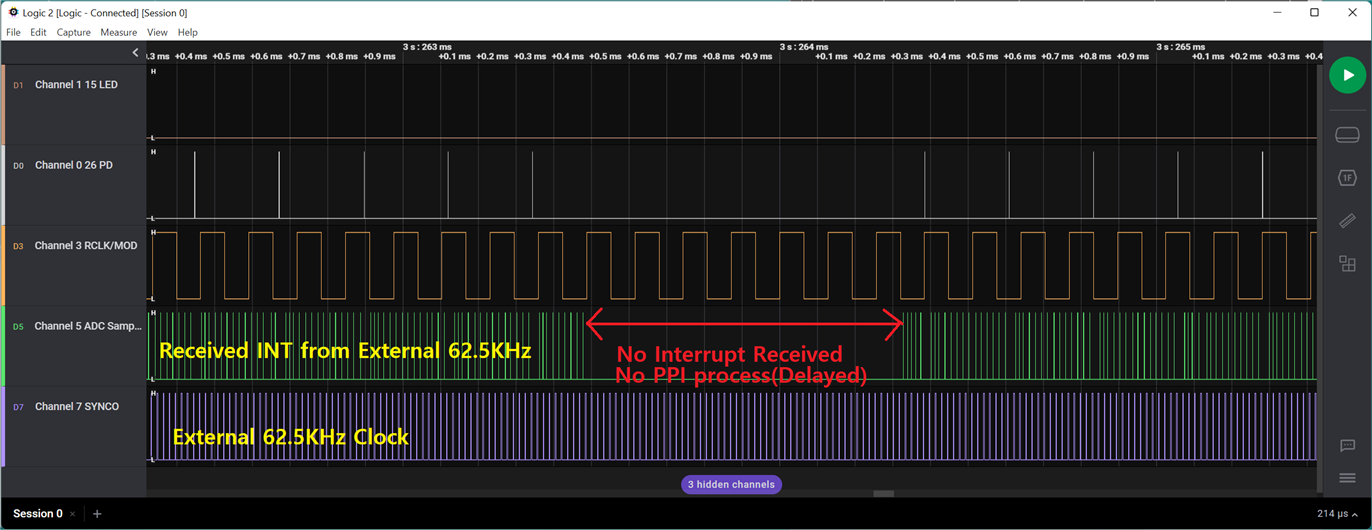
However, sometimes PPI processing is delayed(No interrupt received) as shown in the following figure. What could be the reason for this?


I guess the ability to receive an external 62.5KHz as an interrupt is delayed because of the interrupt inhibition of the MCU.
Is there a way to solve this interrupt receive delay and PPI delay?

Best Regards,

SunBae Yim.

  • Here is my source code:

    /*******************************************************************************
     * @file	meas_pd_voltage_simple.c
     * @author	
     * @version	V1.0.0
     * @date	2022-09-05
     * @brief   
     ******************************************************************************/
    
    #include "sdk_common.h"
    			
    #include <stdbool.h>
    #include <stdint.h>
    #include <stdio.h>
    #include <string.h>
    #include "nrf.h"
    #include "boards.h"
    #include "app_error.h"
    #include "nrf_drv_saadc.h"
    #include "nrfx_gpiote.h"
    #include "nrf_drv_gpiote.h"
    #include "nrf_drv_ppi.h"
    #include "nrf_drv_timer.h"
    #include "nrf_delay.h"
    #include "ada2200_spi.h"
    #include "battery_saadc.h"
    #include "ble_nus.h"
    #include "meas_pd_voltage_simple.h"
    #include "main.h"
    
    #define PD_REF_VOLTAGE_IN_MILLIVOLTS   		600.0f                                     /**< Reference voltage (in milli volts) used by ADC while doing conversion. */
    #define PD_PRE_SCALING_COMPENSATION    		6.0f                                       /**< The ADC is configured to use VDD with 1/3 prescaling as input. And hence the result of conversion is to be multiplied by 3 to get the actual value of the battery voltage.*/
    #define PD_ADC_RES_10BITS             		1024.0f                                    /**< Maximum digital value for 10-bit ADC conversion. */
    
    /**@brief Macro to convert the result of ADC conversion in millivolts.
     *
     * @param[in]  ADC_VALUE   ADC result.
     *
     * @retval     Result converted to millivolts.
     */
    #define PD_VOUT_IN_MILLI_VOLTS(ADC_VALUE)\
    				(((((ADC_VALUE) * PD_REF_VOLTAGE_IN_MILLIVOLTS) / PD_ADC_RES_10BITS) * PD_PRE_SCALING_COMPENSATION)*2)
    
    #define SIM_SAMPLES_IN_BUFFER 		1
    
    static nrf_saadc_value_t pd_adc_buf[2][SIM_SAMPLES_IN_BUFFER];
    bool  pd_adc_simple_start	= false;
    bool  pd_adc_simple_end		= false;
    
    #define PD_ADC_CNT			8
    uint8_t SIM_IRQ_NO 			= 8;
    
    float pd_voltage_buff[35]; /* For Cycle-8, Cycle-16, Cycle-24, Cycle-32 */ 
    uint8_t	pd_voltage_buff_idx = 0;
    
    static nrf_ppi_channel_t	m_ppi_channel;
    
    extern char		ble_tx_buffer[BLE_NUS_MAX_DATA_LEN];
    
    
    void simple_ppi_init(void)
    {
        ret_code_t err_code;
    
        err_code = nrf_drv_ppi_init();
        APP_ERROR_CHECK(err_code);
    
        uint32_t gpiote_event_addr = nrf_drv_gpiote_in_event_addr_get(ADA2200_SYNCO_PIN);	
        uint32_t saadc_sample_task_addr   = nrf_drv_saadc_sample_task_get();
    
        /* setup ppi channel so that timer compare event is triggering sample task in SAADC */
        err_code = nrf_drv_ppi_channel_alloc(&m_ppi_channel);
        APP_ERROR_CHECK(err_code);
    
        err_code = nrf_drv_ppi_channel_assign(m_ppi_channel,
                                              gpiote_event_addr,
                                              saadc_sample_task_addr);
        APP_ERROR_CHECK(err_code);
    }
    
    
    void simple_ppi_uninit(void)
    {
        ret_code_t err_code;
    
        err_code = nrf_drv_ppi_uninit();
        APP_ERROR_CHECK(err_code);
    }
    
    
    void simple_sampling_event_enable(void)
    {
        ret_code_t err_code = nrf_drv_ppi_channel_enable(m_ppi_channel);
        APP_ERROR_CHECK(err_code);
    }
    
    
    void simple_sampling_event_disable(void)
    {
    	ret_code_t err_code = nrf_drv_ppi_channel_disable(m_ppi_channel);
    	APP_ERROR_CHECK(err_code);
    }
    
    
    /**@brief Function for handling the ADC interrupt.
     *
     * @details  This function will fetch the conversion result from the ADC, convert the value into
     *           percentage and send it to peer.
     */
    static void simple_voltage_handler(nrf_drv_saadc_evt_t const * p_event)	/* PD Voltage reading */
    {
    	
    	float pd_voltage_sum = 0.0f;
    
        if (p_event->type == NRF_DRV_SAADC_EVT_DONE)
        {	
    #if FEATURE_FOR_SCOPE    
    		nrf_gpio_pin_set(ADC_CLK_18);
    		nrf_gpio_pin_clear(ADC_CLK_18);
    #endif	
    	
            ret_code_t err_code = nrf_drv_saadc_buffer_convert(p_event->data.done.p_buffer, SIM_SAMPLES_IN_BUFFER);
    		APP_ERROR_CHECK(err_code);
    
    		pd_voltage_buff[pd_voltage_buff_idx] = p_event->data.done.p_buffer[0];
    		pd_voltage_buff_idx++;
    
    		if(pd_voltage_buff_idx == SIM_IRQ_NO) {
    			pd_adc_simple_end = true;
    			pd_adc_simple_start = false;
    
    			simple_mesurement_stop();
    
    			pd_voltage_sum = 0;
    
    			for(uint8_t i = 0; i < SIM_IRQ_NO; i++) {
    				
    				pd_voltage_buff[i] = PD_VOUT_IN_MILLI_VOLTS(pd_voltage_buff[i]);
    				pd_voltage_buff[i] = pd_voltage_buff[i] * -1;
    				pd_voltage_sum += pd_voltage_buff[i];
    			}
    
    			for(uint8_t i = 0; i < SIM_IRQ_NO; i++) {
    				printf(" %f ", pd_voltage_buff[i]);
    			}
    
    			printf("\r\nTh%f\r\n\r\n", pd_voltage_sum);
    			sprintf(ble_tx_buffer, "Th%f\r\n", pd_voltage_sum);
    			data_tx_handler(ble_tx_buffer);
    		}
        }
    }
    
    
    void simple_adc_init(void)
    {
    	static nrfx_saadc_config_t default_config;
    	default_config.resolution 			= (nrf_saadc_resolution_t)NRFX_SAADC_CONFIG_RESOLUTION;	/* Resolution is 10bits */
    	default_config.oversample 			= (nrf_saadc_oversample_t)NRFX_SAADC_CONFIG_OVERSAMPLE;	/* Over Sampling Disabled */
    	default_config.interrupt_priority 	= NRFX_SAADC_CONFIG_IRQ_PRIORITY;						/* Interrupt Priority is 0(Highest) */
    	default_config.low_power_mode 		= NRFX_SAADC_CONFIG_LP_MODE;							/* Low Power Mode is Disabled */
    
    	static nrf_saadc_channel_config_t config;
    	config.resistor_p 	= NRF_SAADC_RESISTOR_DISABLED;
    	config.resistor_n 	= NRF_SAADC_RESISTOR_DISABLED;
    	config.gain			= NRF_SAADC_GAIN1_6;
    	config.reference	= NRF_SAADC_REFERENCE_INTERNAL;
    	config.acq_time		= NRF_SAADC_ACQTIME_3US;
    	config.mode			= NRF_SAADC_MODE_DIFFERENTIAL;
    	config.burst		= NRF_SAADC_BURST_DISABLED;
    	config.pin_p		= (nrf_saadc_input_t)(NRF_SAADC_INPUT_AIN0);
    	config.pin_n		= (nrf_saadc_input_t)(NRF_SAADC_INPUT_AIN1);
    	
    	ret_code_t err_code = nrf_drv_saadc_init(&default_config, simple_voltage_handler);
    	APP_ERROR_CHECK(err_code);
    
    	err_code = nrf_drv_saadc_channel_init(0, &config);
    	APP_ERROR_CHECK(err_code);
    
    	err_code = nrf_drv_saadc_buffer_convert(pd_adc_buf[0], SIM_SAMPLES_IN_BUFFER);
    	APP_ERROR_CHECK(err_code);
    
    //	err_code = nrf_drv_saadc_buffer_convert(pd_adc_buf[1], SIM_SAMPLES_IN_BUFFER);
    //	APP_ERROR_CHECK(err_code);
    }
    
    
    void simple_adc_uninit(void)
    {
    	nrf_drv_saadc_uninit();
    	nrf_drv_saadc_channel_uninit(0);
    }
    
    
    void simple_irq_init(void){
        ret_code_t err_code;
    
    	/* Initialize int pin */
    	if (!nrfx_gpiote_is_init())
    	{
    	  err_code = nrfx_gpiote_init();
    	  APP_ERROR_CHECK(err_code);
    	}
    
        nrfx_gpiote_in_config_t in_config = NRFX_GPIOTE_CONFIG_IN_SENSE_LOTOHI(true);
        in_config.pull = NRF_GPIO_PIN_PULLDOWN;
    
        err_code = nrfx_gpiote_in_init(ADA2200_SYNCO_PIN, &in_config, NULL);
        APP_ERROR_CHECK(err_code);
    
        nrfx_gpiote_in_event_enable(ADA2200_SYNCO_PIN, true);
    }
    
    
    void simple_irq_uninit(void){
    
    	nrfx_gpiote_in_event_disable(ADA2200_SYNCO_PIN);
    	nrfx_gpiote_in_uninit(ADA2200_SYNCO_PIN);
    }
    
    
    void simple_mesurement_start(void){
    
    	battery_timer_stop();
    
    	simple_irq_init();
    	simple_adc_init();
    	simple_ppi_init();
    
    	simple_sampling_event_enable();
    }
    
    
    void simple_mesurement_stop(void){
    
    	battery_timer_start();
    
    	simple_sampling_event_disable();
    	simple_adc_uninit();
    	simple_ppi_uninit();
    	simple_irq_uninit();
    }
    

    Looking at simple_voltage_handler() in my source code, I make GPIO High->Low as follows.

    #if FEATURE_FOR_SCOPE
    nrf_gpio_pin_set(ADC_CLK_18);
    nrf_gpio_pin_clear(ADC_CLK_18);
    #endif

    This code represents a green clock. And the lag appears.

  • I set SIM_IRQ_NO to 16 in the code.
    The register value is saved in the RAM Buffer pd_voltage_buff while performing ADC sampling 16 times.
    I am only doing the same ADC sampling. But why would the delay happen?

    After 16 samplings are completed, the value is changed to voltage, LOG is displayed, and the value is transmitted through BLE.

    Why is there a delay when the ADC only samples through the PPI?
    please help me.

    Best Regards.

    SunBae Yim.

  • Hello again, SunBae Yim

    ParanBada said:
    Why is there a delay when the ADC only samples through the PPI?

    Thank you for sharing the source code used for the measuring.
    The GPIO is being set by the CPU when it goes to process the SAADC DONE event, which is not necessarily immediately after the SAADC has performed a sampling. The CPU could be busy handling a higher level interrupt, such as any SoftDevice activity, and thus the processing of the DONE event could be delayed. This is likely what is happening in your measurements.

    If you want the GPIO to accurately portray when the DONE event occurs you should instead have a PPI channel connect the DONE event and a GPIO toggle task. This way, you will see that the DONE event is actually generated as soon as the sampling finishes, which should be [t_CONV + t_ACQ] after the 62.5 kHz pulse.

    Additionally, I also note that you are using a SAADC buffer size of 1, which means that the CPU needs to intervene for every sample to provide the next buffer to use by the ADC. Instead, I would recommend increasing the SAADC buffer to a higher number, so that you only need to do processing every so often, instead of after each sampling.

    Best regards,
    Karl

  • Hello,

    Your advice to increase the SAADC buffer size is good.
    How many SAADC buffers can I increase?
    Is there any documentation to refer to the SAADC buffer max size?

    I want to set the SAADC Buffer size to 4127. Is it possible?

    Best Regards,

    SunBae Yim.

  • Hello again, SunBae Yim

    ParanBada said:
    Your advice to increase the SAADC buffer size is good.

    I am glad to hear you say so! :)

    ParanBada said:

    Is there any documentation to refer to the SAADC buffer max size?

    I want to set the SAADC Buffer size to 4127. Is it possible?

    The SAADC uses EasyDMA and so the provided buffer must be in RAM.
    Additionally, the maximum value of the MAXCNT register is 2^14 -1, and so that is the maximal buffer size for a single buffer.
    You can read more about this in the SAADC EasyDMA documentation.

    Best regards,
    Karl

Related