PPI delay due to interrupt disable.

Hello,
I implemented the function to receive an external 62.5KHz clock as an interrupt and repeat the process at a very regular time using PPI.
However, sometimes PPI processing is delayed(No interrupt received) as shown in the following figure. What could be the reason for this?
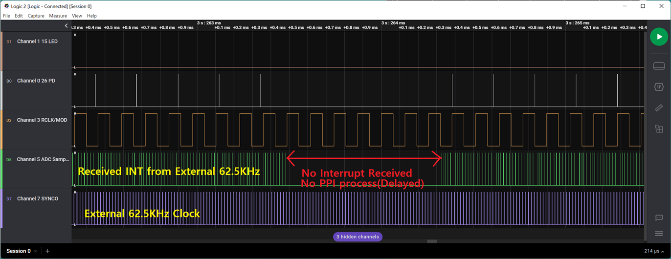

I guess the ability to receive an external 62.5KHz as an interrupt is delayed because of the interrupt inhibition of the MCU.
Is there a way to solve this interrupt receive delay and PPI delay?

Best Regards,

SunBae Yim.

  • Hello,

    ADC sampling using the PPI function. Where is the source code for that part?
    Is it done inside the soft device? Or does it not work on the hardware inside the MCU?

    I want to check the code that works when performing ADC sampling through PPI.
    For example, if the SAADC buffer size is 100, ADC sampling is executed 100 times and the value is stored in this RAM buffer.
    Whenever ADC sampling is performed 100 times, I want to control the GPIO port in that part of the source code as follows.

    #if FEATURE_FOR_SCOPE
    nrf_gpio_pin_set(ADC_CLK_18);
    nrf_gpio_pin_clear(ADC_CLK_18);
    #endif

    Then I want to check 100 ADC samplings through a logic analyzer.

    Best Regards,

    SunBae Yim.

  • Hello SunBae Yim,

    ParanBada said:
    ADC sampling using the PPI function. Where is the source code for that part?

    If you just would like to see how to trigger SAADC sampling through PPI then you could take a look at the SAADC example in the SDK.
    You could also see some examples of common SAADC usage in this repository.

    ParanBada said:
    Is it done inside the soft device?

    No - the SoftDevice does use some PPI channels, but your application can use the channels that are not being used by the SoftDevice for whatever you would like.

    ParanBada said:
    Or does it not work on the hardware inside the MCU?

    I am not sure that I understand this question, could you elaborate?

    ParanBada said:
    For example, if the SAADC buffer size is 100, ADC sampling is executed 100 times and the value is stored in this RAM buffer.
    Whenever ADC sampling is performed 100 times, I want to control the GPIO port in that part of the source code as follows.

    To achieve this you could set the GPIO as part of the DONE handling - just keep in mind that the processing of the DONE event could be postponed if there is a higher priority interrupt being processed at the time where it is generated, so the GPIO will then not show exactly when the 100 samples have completed.
    If you want the GPIO to accurately reflect when the 100 samples have been collected you would have to set up a PPI channel between the GPIO and the SAADC DONE event - in this case, it would toggle immediately when the DONE event is generated.

    Best regards,
    Karl

Related